Sequential Circuits & Finite State Machines Overview
Dive into the realm of sequential circuits and finite state machines through topics like adder wrap-up, clock coordination in microprocessors, and the importance of latches in ensuring data stability. Discover the trade-offs in performance with different adder designs and learn about clock terminology and its significance in circuit synchronization. Explore how sequential circuits differentiate from combinational circuits and the role of clocks in regulating circuit operations.

Download Presentation

Please find below an Image/Link to download the presentation.
The content on the website is provided AS IS for your information and personal use only. It may not be sold, licensed, or shared on other websites without obtaining consent from the author.If you encounter any issues during the download, it is possible that the publisher has removed the file from their server.
You are allowed to download the files provided on this website for personal or commercial use, subject to the condition that they are used lawfully. All files are the property of their respective owners.
The content on the website is provided AS IS for your information and personal use only. It may not be sold, licensed, or shared on other websites without obtaining consent from the author.
E N D
Presentation Transcript
Lecture 14: Sequential Circuits, FSM Today s topics: Adder wrap-up Sequential circuits Finite state machines 1
Adder Summary Using the generate/propagate abstraction to add layers of ccts Key: all g/p/G/P signals can be calculated based on a/b inputs (they don t need carry-in as inputs, so they can all be done rightaway in parallel) First calculate g/p with 1 gate delay: gi = ai.bi ; pi = ai + bi Then calculate G/P with up to 2 gate delays (for a block of 4 bits): Gi = g3 + g2.p3 + g1.p2.p3 + g0.p1.p2.p3 Pi = p0.p1.p2.p3 Then calculate all the carries, including for the 16th bit, with 2 more gate delays: C4 = G3 + (P3.G2) + (P3.P2.G1) + (P3.P2.P1.G0) + (P3.P2.P1.P0.c0) Thus, this abstraction enables a design with a modest number of total gates, a modest number of delays, and a modest number of inputs per gate. 2
Trade-Off Curve Performance Truth table sum-of-products adder, (2, 264) #inputs to each gate # sequential gates gp adder (3, 33) Carry Lookahead GP adder (7, 5) Ripple-Carry adder (64, 2) # sequential gates 3
Clocks A microprocessor is composed of many different circuits that are operating simultaneously if each circuit X takes in inputs at time TIX, takes time TEX to execute the logic, and produces outputs at time TOX, imagine the complications in co-ordinating the tasks of every circuit A major school of thought (used in most processors built today): all circuits on the chip share a clock signal (a square wave) that tells every circuit when to accept inputs, how much time they have to execute the logic, and when they must produce outputs 4
Clock Terminology Rising clock edge Cycle time Falling clock edge 4 GHz = clock speed = 1 = 1 . cycle time 250 ps 5
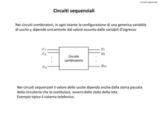
Sequential Circuits Until now, circuits were combinational when inputs change, the outputs change after a while (time = logic delay thru circuit) Combinational Circuit Combinational Circuit Outputs Inputs We want the clock to act like a start and stop signal a latch is a storage device that separates these circuits it ensures that the inputs to the circuit do not change during a clock cycle Clock Clock Outputs Combinational Circuit Combinational Circuit Inputs Latch Latch 6
Sequential Circuits Sequential circuit: consists of combinational circuit and a storage element Inputs State Clock Inputs Outputs At the start of the clock cycle, the rising edge causes the state storage to store some input values Combinational Cct This state will not change for an entire cycle (until next rising edge) The combinational circuit has some time to accept the value of state and inputs and produce outputs Some of the outputs (for example, the value of next state ) may feed back (but through the latch so they re only seen in the next cycle) 7
Designing a Latch An S-R latch: set-reset latch When Set is high, a 1 is stored When Reset is high, a 0 is stored When both are low, the previous state is preserved (hence, known as a storage or memory element) Both are high this set of inputs is not allowed Verify the above behavior! 8 Source: H&P textbook
D Latch Incorporates a clock The value of the input D signal (data) is stored only when the clock is high the previous state is preserved when the clock is low 9 Source: H&P textbook
D Flip Flop Terminology: Latch: outputs can change any time the clock is high (asserted) Flip flop: outputs can change only on a clock edge Two D latches in series ensures that a value is stored only on the falling edge of the clock 10 Source: H&P textbook
Finite State Machine A sequential circuit is described by a variation of a truth table a finite state diagram (hence, the circuit is also called a finite state machine) Note that state is updated only on a clock edge Next state Next-state Function Current State Clock Outputs Output Function Inputs 11
State Diagrams Each state is shown with a circle, labeled with the state value the contents of the circle are the outputs An arc represents a transition to a different state, with the inputs indicated on the label D = 0 D = 1 This is a state diagram for ___? D = 1 0 1 0 1 D = 0 12
3-Bit Counter Consider a circuit that stores a number and increments the value on every clock edge on reaching the largest value, it starts again from 0 Draw the state diagram: How many states? How many inputs? 13
3-Bit Counter Consider a circuit that stores a number and increments the value on every clock edge on reaching the largest value, it starts again from 0 Draw the state diagram: How many states? How many inputs? 000 001 010 011 100 101 110 111 000 001 010 011 100 101 110 111 14
Tackling FSM Problems Three questions worth asking: What are the possible output states? Draw a bubble for each. What are inputs? What values can those inputs take? For each state, what do I do for each possible input value? Draw an arc out of every bubble for every input value. 15
Traffic Light Controller Problem description: A traffic light with only green and red; either the North-South road has green or the East-West road has green (both can t be red); there are detectors on the roads to indicate if a car is on the road; the lights are updated every 30 seconds; a light need change only if a car is waiting on the other road State Transition Table: How many states? How many inputs? How many outputs? 16
State Transition Table Problem description: A traffic light with only green and red; either the North-South road has green or the East-West road has green (both can t be red); there are detectors on the roads to indicate if a car is on the road; the lights are updated every 30 seconds; a light must change only if a car is waiting on the other road State Transition Table: CurrState InputEW InputNS NextState=Output N 0 0 N N 0 1 N N 1 0 E N 1 1 E E 0 0 E E 0 1 N E 1 0 E E 1 1 N 17
State Diagram State Transition Table: CurrState InputEW InputNS NextState=Output N 0 0 N N 0 1 N N 1 0 E N 1 1 E E 0 0 E E 0 1 N E 1 0 E E 1 1 N 18 Source: H&P textbook
Tackling FSM Problems Three questions worth asking: What are the possible output states? Draw a bubble for each. What are inputs? What values can those inputs take? For each state, what do I do for each possible input value? Draw an arc out of every bubble for every input value. 19
Example Residential Thermostat Two temp sensors: internal and external If internal temp is within 1 degree of desired, don t change setting If internal temp is > 1 degree higher than desired, turn AC on; if internal temp is < 1 degree lower than desired, turn heater on If external temp and desired temp are within 5 degrees, disregard the internal temp, and turn both AC and heater off 20
Finite State Diagram U-H U-C, U-G U-H, U-G HEAT COOL U-C U-C U-H D-C, D-G, D-H D-C, D-G, D-H Int temp settings: C cold G goldilocks H hot OFF Ext temp settings: D desired zone U undesired zone D-C, D-G, D-H, U-G 22
Latch vs. Flip-Flop Recall that we want a circuit to have stable inputs for an entire cycle so I want my new inputs to arrive at the start of a cycle and be fixed for an entire cycle A flip-flop provides the above semantics (a door that swings open and shut at the start of a cycle) But a flip-flop needs two back-to-back D-latches, i.e., more transistors, delay, power You can reduce these overheads with just a single D-latch (a door that is open for half a cycle) as long as you can tolerate stable inputs for just half a cycle 23