Hierarchical Verilog Code Structure

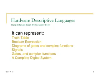
Different examples of Verilog adder circuits explained through gate-level, behavioral, and procedural statements. Learn about structural and modular descriptions, continuous assignment, encoding methods, and more to enhance your understanding of digital logic design.

Download Presentation

Please find below an Image/Link to download the presentation.
The content on the website is provided AS IS for your information and personal use only. It may not be sold, licensed, or shared on other websites without obtaining consent from the author.If you encounter any issues during the download, it is possible that the publisher has removed the file from their server.
You are allowed to download the files provided on this website for personal or commercial use, subject to the condition that they are used lawfully. All files are the property of their respective owners.
The content on the website is provided AS IS for your information and personal use only. It may not be sold, licensed, or shared on other websites without obtaining consent from the author.
E N D
Presentation Transcript
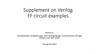
Supplement on Verilog adder examples Based on Fundamentals of Digital Logic with Verilog Design By Brown/Vranesic 3rd. Chung-Ho Chen 1
Describe a circuit in a form of module Gate Level: structural description and (u, ~s, x1); // without an explicit not ahead module mux (x1, x2, s, f); input x1, x2, s; output f; keyword not (si,s); and (u, si, x1); and (l, s, x2); or (f, u, l); endmodule output 2
Behavioral: logic equation module mux (x1, x2, s, f); input x1, x2, s; output f; Continuous assignment: f is re-evaluated whenever the right hand side signal changes. assign f = (~s & x1) | (s &x2); assign y = f | x2; No order for f and y, concurrent statement; assign: for nets (like wire) since nets can not hold values, so you need to assign the value continuously. endmodule 3
Behavioral: procedural statement The simulator registers this value until the always block is executed again. module mux (x1, x2, s, f); input x1, x2, s; output f; reg f; always@(sensitivity list) always@(x1 or x2 or s) if (s == 0) f = x1; else f = x2; Evaluated in the order given by the code; if first, then else. = blocking assignment (evaluated in order) endmodule 4
Coding in 3 ways: Gate instantiation Continuous assignment (assign) An assign statement is used for modeling only combinational logic and it is executed continuously. So the assign statement is called 'continuous assignment statement' as there is no sensitive list. Procedural statements (always) Blocking assignment = sequencing S = X + Y; // S[3:0] C = S[0]; // C takes the new value from X+Y. Non-blocking assignment <= S <= X + Y; C <= S[0]; // at simulation time ti, C takes the value of S[0] at simulation time ti-1 5
More compact procedural statement module mux (input x1, x2, s, output reg f); always@(x1, x2,s) if (s == 0) f = x1; else f = x2; endmodule 6
Hierarchical Verilog Code Hierarchical Verilog Code Top-level module module whole (X1, X2, A, B, C, D, E); Input X1, X2; output A, B, C, D, E; wire w0, w1; a b c d e A B C D E w0 X1 a c y1 b d y2 X2 w1 front U1 (X1, X2, w0, w1); back U2 (w0, w1, A, B, C, D, E); .. endmodule module front (a, b, c, d); Input a, b; output c, d; .. endmodule module back (y1, y2, a, b, c, d, e); Input y1, y2; output a, b, c, d, e; .. endmodule Internal (not output or input) uses wire. 7
Full Adder Full Adder U Using sing G Gates ates x i y i c i 00 01 11 10 module fulladd (Cin, x, y, s, Cout); input Cin, x, y; output s, Cout; 1 1 0 c i x i y i s i i c + 1 1 1 1 0 0 0 0 1 1 1 1 0 0 1 1 0 0 1 1 0 1 0 1 0 1 0 1 0 0 0 1 0 1 1 1 0 1 1 0 1 0 0 1 = s i x i y i c i x i y i module fulladd (Cin, x, y, s, Cout); input Cin, x, y; output s, Cout; c i 00 01 11 10 xor (s, x, y, Cin); and (a, x, y); and (b, x, Cin); and (c, y, Cin); or (Cout, a, b, c); 1 0 1 1 1 1 (a) Truth table = + + c i x i y i x i c i y i c i + 1 (b) Karnaugh maps xor (s, x, y, Cin); and (a, x, y), (b, x, Cin), //omit and (c, y, Cin); or (Cout, a, b, c); x i y i s i endmodule c i endmodule c i + 1 (c) Circuit 8
Full Adder Full Adder U Using sing F Functional unctional E Expression xpression x i y i c i 00 01 11 10 1 1 0 c i x i y i s i i c + 1 1 1 1 0 0 0 0 1 1 1 1 0 0 1 1 0 0 1 1 0 1 0 1 0 1 0 1 0 0 0 1 0 1 1 1 0 1 1 0 1 0 0 1 = s i x i y i c i module fulladd (Cin, x, y, s, Cout); input Cin, x, y; output s, Cout; assign s = x ^ y ^ Cin, Cout = (x & y) | (x & Cin) | (y & Cin); endmodule x i y i c i 00 01 11 10 1 0 1 1 1 1 (a) Truth table = + + c i 1 + x i y i x i c i y i c i (b) Karnaugh maps x i y i s i c i c i 1 + (c) Circuit 9
3 3- -bit Ripple Adders bit Ripple Adders module adder3 (c0, x2, x1, x0, y2, y1, y0, s2, s1, s0, carryout); input c0, x2, x1, x0, y2, y1, y0; output s2, s1, s0, carryout; fulladd b0 (c0, x0, y0, s0, c1); fulladd b1 (c1, x1, y1, s1, c2); fulladd b2 (c2, x2, y2, s2, carryout); endmodule Instantiate the fulladd module module fulladd (Cin, x, y, s, Cout); input Cin, x, y; output s, Cout; assign s = x ^ y ^ Cin, assign Cout = (x & y) | (x & Cin) | (y & Cin); endmodule 10
3 3- -bit Ripple Adders Using Vectored Signals bit Ripple Adders Using Vectored Signals Vectored signals used module adder3 (c0, x2, x1, x0, y2, y1, y0, s2, s1, s0, carryout); input c0, x2, x1, x0, y2, y1, y0; output s2, s1, s0, carryout; module adder3 (c0, X, Y, S, carryout); input c0; input [2:0] X, Y; output [2:0] S; output carryout; wire [2:1] C; fulladd b0 (c0, x0, y0, s0, c1); fulladd b1 (c1, x1, y1, s1, c2); fulladd b2 (c2, x2, y2, s2, carryout); endmodule fulladd b0 (c0, X[0], Y[0], S[0], C[1]); fulladd b1 (C[1], X[1], Y[1], S[1], C[2]); fulladd b2 (C[2], X[2], Y[2], S[2], carryout); module fulladd (Cin, x, y, s, Cout); input Cin, x, y; output s, Cout; endmodule assign s = x ^ y ^ Cin, assign Cout = (x & y) | (x & Cin) | (y & Cin); endmodule 11
n n- -bit Ripple Adders bit Ripple Adders module adderN (c0, X, Y, S, carryout); parameter n = 16; input c0; input [n-1:0] X, Y; output reg [n-1:0] S; output reg carryout; reg [n:0] C; integer k; always @(X, Y, c0) begin C[0] = c0; for (k = 0; k < n; k = k+1) begin 1: for: a procedural statement, must be inside a always block. for loop in Verilog specifies a different subcircuit in each iteration. for loop does not specify change that takes place in time during successive iterations as in a programming language. 2: Values inside a always block must retain their values until any change of signals in the sensitivity list. To hold on the values, use reg to keep them. There is no physical meaning of k in the circuit. It is used to tell the compiler that how many instances of the iteration are needed. S[k] = X[k] ^ Y[k] ^ C[k]; C[k+1] = (X[k] & Y[k]) | (X[k] & C[k]) | (Y[k] & C[k]); end carryout = C[n]; end endmodule 12
3 3- -bit to n bit to n- -bit transformation using bit transformation using generate generate module addern (c0, X, Y, S, carryout); parameter n = 16; input c0; input [n-1:0] X, Y; output [n-1:0] S; output carryout; wire [n:0] C; module adder3 (c0, X, Y, S, carryout); input c0; input [2:0] X, Y; output [2:0] S; output carryout; wire [2:1] C; Instantiate a submodule n times using generate fulladd b0 (c0, X[0], Y[0], S[0], C[1]); fulladd b1 (C[1], X[1], Y[1], S[1], C[2]); fulladd b2 (C[2], X[2], Y[2], S[2], carryout); genvar i; // to be used in generate assign C[0] = c0; assign carryout = C[n]; generate for (i = 0; i <= n-1; i = i+1) begin:adderbit fulladd b (C[i], X[i], Y[i], S[i], C[i+1]); end endgenerate endmodule endmodule Instance name produced adderbit[0].b adderbit[1].b . adderbit[15].b 13
O Overflow and Carry verflow and Carry- -Out detection Out detection n-bit signed number: -2n-1to 2n-1 -1 For unsigned number carry out from n-1 bit position: Detect overflow for signed number: Overflow = Cn-1 C Cn n If both xn-1and yn-1are 1 or If either xn-1or yn-1is 1 and sn-1is 0. Overflow = Xn-1Yn-1~Sn-1(110) + ~Xn-1~Yn-1Sn-1(001) (summation of two same signs produce different sign) Hence, carryout = xn-1yn-1 +~sn-1 xn-1+ ~sn-1yn-1 where X and Y represent the 2 s complement numbers, S = X+Y. (sign bits 0, 0 1 ) 0111 0111 1111 x or y carryin 1 1 0 14
n-bit adder with overflow and carryout module addern (carryin, X, Y, S, carryout, overflow); parameter n = 32; input carryin; input [n-1:0] X, Y; output reg [n-1:0] S; output reg carryout, overflow; always @(X, Y, carryin) begin S = X + Y + carryin; // arithmetic assignment carryout = (X[n-1] & Y[n-1]) | (X[n-1] & ~S[n-1]) | (Y[n-1] & ~S[n-1]); overflow = (X[n-1] & Y[n-1] & ~S[n-1]) | (~X[n-1] & ~Y[n-1] & S[n-1]); end endmodule 15
Another way to get carryout module addern (carryin, X, Y, S, carryout, overflow); parameter n = 32; input carryin; input [n-1:0] X, Y; output reg [n-1:0] S; output reg carryout, overflow; reg [n:0] Sum; //n+1 bits, nthfor the carryout always @(X, Y, carryin) begin Sum = {1'b0,X} + {1'b0,Y} + carryin; // One 0 bit is concatenated (,) with X S = Sum[n-1:0]; carryout = Sum[n]; overflow = (X[n-1] & Y[n-1] & ~S[n-1]) | (~X[n-1] & ~Y[n-1] & S[n-1]); end Will this work? Sum = X + Y + carryin;? endmodule 16
Better module addern (carryin, X, Y, S, carryout, overflow); parameter n = 32; input carryin; input [n-1:0] X, Y; output reg [n-1:0] S; output reg carryout, overflow; always @(X, Y, carryin) begin {carryout, S} = X + Y + carryin; //using concatenation overflow = (X[n-1] & Y[n-1] & ~S[n-1]) | (~X[n-1] & ~Y[n-1] & S[n-1]); end endmodule 17
Module Hierarchy in Verilog two adders: 16-bit and 8-bit module adder_hier (A, B, C, D, S, T, overflow); input [15:0] A, B; input [7:0] C, D; output [16:0] S; output [8:0] T; output overflow; module addern (carryin, X, Y, S, carryout, overflow); parameter n = 32; input carryin; input [n-1:0] X, Y; output reg [n-1:0] S; output reg carryout, overflow; wire v1, v2; // used for the overflow signals always @(X, Y, carryin) begin {carryout, S} = X + Y + carryin; overflow = (X[n-1] & Y[n-1] & ~S[n- 1]) | (~X[n-1] & ~Y[n-1] & S[n-1]); end defparam: define n to be 16 addern U1 (1 b0, A, B, S[15:0], S[16], v1); defparam U1.n = 16; addern U2 (1 b0, C, D, T[7:0], T[8], v2); defparam U2.n = 8; S[16] and T[8] for unsigned carryout endmodule assign overflow = v1 | v2; endmodule 18
Specifying Parameters two adders: 16-bit and 8-bit module adder_hier (A, B, C, D, S, T, overflow); input [15:0] A, B; input [7:0] C, D; output [16:0] S; output [8:0] T; output overflow; // not in an always block Using # operator. addern #(16) U1 (1 b0, A, B, S[15:0], S[16], v1); wire v1, v2; // used for the overflow signals addern U1 (1 b0, A, B, S[15:0], S[16], v1); defparam U1.n = 16; addern U2 (1 b0, C, D, T[7:0], T[8], v2); defparam U2.n = 8; assign overflow = v1 | v2; endmodule 19
Named port connection module adder_16(A, B, S, overflow); input [15:0] A, B; output [16:0] S; output overflow; // not in an always block wire v1; // used for the overflow signals module addern (carryin, X, Y, S, carryout, overflow); parameter n = 32; input carryin; input [n-1:0] X, Y; output reg [n-1:0] S; output reg carryout, overflow; addern #(.n(16)) U1 ( .carryin(1 b0), .X (A), .Y (B), .S (S[15:0), .carryout (S[16]), .overflow (v1) ); assign overflow = v1; always @(X, Y, carryin) begin {carryout, S} = X + Y + carryin; overflow = (X[n-1] & Y[n-1] & ~S[n-1]) | (~X[n-1] & ~Y[n-1] & S[n-1]); end endmodule endmodule 20
So far, nets and variables Net: connecting things. Represent structural connections between components. wire. A wire connects an output of one logic element to the input of another logic element. No need to declare scalar signals of wire, since signals are nets by default. tri. Another net is tri denoting circuit nodes which are connected in tri-state. Variable: used to describe behaviors of the circuits. reg. Represent variables. reg does not denote a storage element or register. reg can model either combinational or sequential part of the circuit. integer. 21