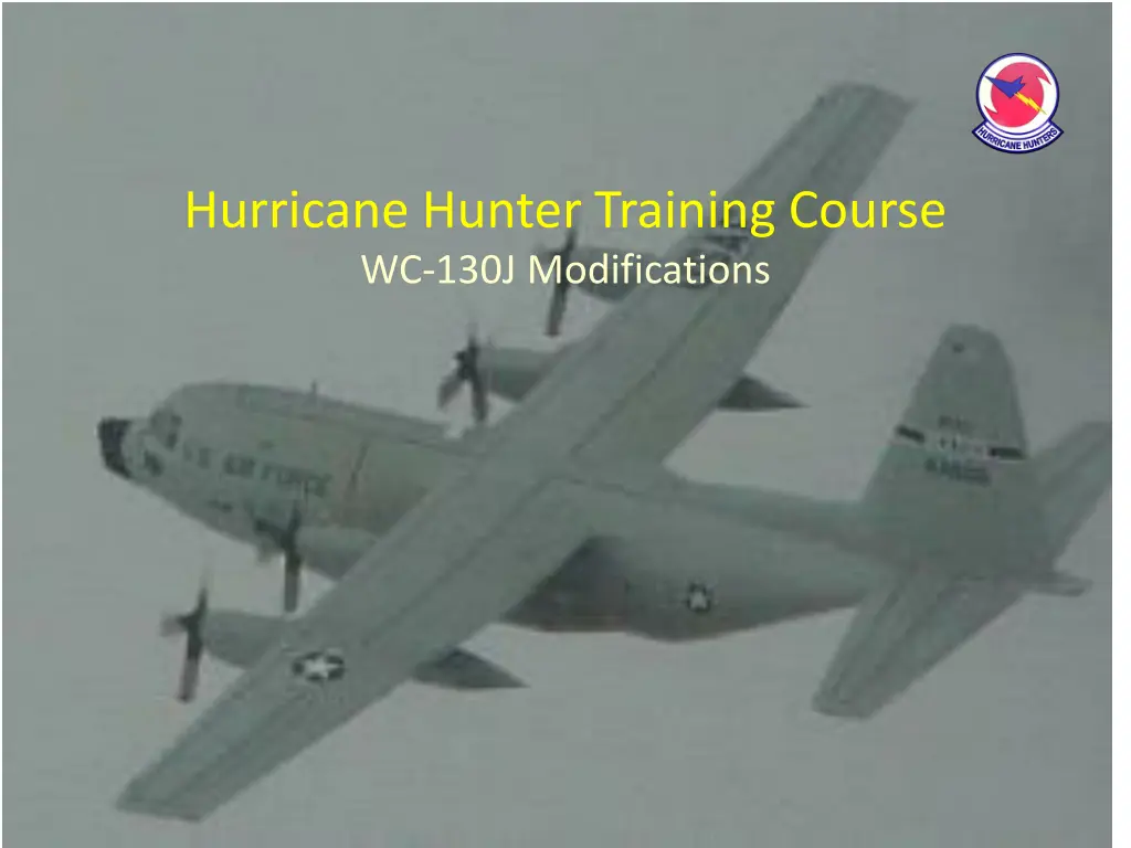
Hurricane Hunter WC-130J Training Course Modifications
Explore the modifications in the Hurricane Hunter Training Course WC-130J, including changes in auto-tilt, attenuation compensation, and pulse compression for radar sensitivity and power output adjustments.

Download Presentation

Please find below an Image/Link to download the presentation.
The content on the website is provided AS IS for your information and personal use only. It may not be sold, licensed, or shared on other websites without obtaining consent from the author. If you encounter any issues during the download, it is possible that the publisher has removed the file from their server.
You are allowed to download the files provided on this website for personal or commercial use, subject to the condition that they are used lawfully. All files are the property of their respective owners.
The content on the website is provided AS IS for your information and personal use only. It may not be sold, licensed, or shared on other websites without obtaining consent from the author.
E N D
Presentation Transcript
Hurricane Hunter Training Course WC-130J Modifications
Outline Summary of Changes APN - 241 - How the computer compensates for low power output and the trade-offs Precursor waveform Auto Tilt for weather Coherent Processing Minus the Technical Stuff Digital Raw Data (DRD) Out of Cal Artifacts Using New Functions HDD 6 Move and Nav Data Page
Summary of Modifications Change Auto-tilt to Manual Fully Account of Intervening Attenuation Reduce cone of silence Precursor with first gate approx. Primary minor improvements/adjustments Out of Cal Calculations Digital Raw Data (DRD) Coherent Mode for Range Extension CNI Pages to support HDD move and Nav Data Page
How The Computer Compensates For Low Power Output Attenuation Compensation Algorithm Pulse Compression Making the most of less Wattage Computer Processing of Pulses
Attenuation Compensation Attenuation compensation algorithm determines attenuation in each range-gate, then adjust the next range-gate with this estimate. Any error up front is amplified at longer ranges. The algorithm too much math in public. ( 10 ) R ln 10 2 ( ) x dx 2 2 b 6 P G K K N 2 k r R R 2 0 3 , ) R R = k dBz PCR a ( , SNR r k r e 0 ( ) 1 2 2 4 c kT NF L 0 0 o
Pulse Compression for Dummies The sensitivity of a radar depends on the energy transmitted in the radar pulses This power = peak power X duty cycle Radar pulses are short ( couple of microseconds, thus power is a small fraction of peak power Longer pulses increase power, but sacrifice resolution Solution is to string a number of short coded pulses (13 on the APN-241) together to simulate one long pulse. The tradeoff is: you don t get any information for the time it takes to transmit the first set of pulses
APN-241 uses Pulse compression design to get more average power on the target without losing range resolution. The tradeoff is there is no return information for the first 10% of the range. No display for first 10% No information to put into the attenuation compensation algorithm. Can cause errors in the algorithm.
Start-Up Intervening Attenuation Error Rain within the transmit pulse is NOT measured. The RADAR measures rain by interpreting signal-to-noise amplitude using a calibrated amplitude coefficient . ON Transmit Transmit pulsewidth OFF Intervening Rain ON Receive OFF Range of First Rain Measurement (10% Range Scale)
Pulse Compression vs. the Attenuation Algorithm Radar receives no return information for first 10% of selected range due to Pulse Compression The radar s computer must assume what is rain is present in this area to put a value into the algorithm. An error in the guess has a cumulative effect as range increases.
Computer Processing of Pulses Non-Coherent Weather Mode 16 Packages of pulse pairs (for turbulence) Each package is on a different rf channel frequency (independent measurement) Package measurements are filtered and averaged to reduce error in the estimated mean reflectivity (dBz)
Auto-Tilt Auto-tilt is designed to minimize operator workload by positioning the antenna beam just above the radar range scale horizon (to avoid ground clutter) Disabling auto-tilt means the operator must manually re-position the tilt Advantages consistent display when changing between ranges
11 10 dBz -128 -116 -106 -95 ARINC NWS 9 Auto-Tilt - Changing the Range Scale Changed the Altitude Illuminated by the Antenna -85 -75 -66 -56 -47 -39 -31 -23 -15 -8 -1 6 12 18 24 29 41 29 32 34 37 39 41 43 45 46 47 48 49 50 50 50 8 7 bright band 6 dbZ ARINC 20 Kft 5 Rscale > RHOR 4 3 Rscale ~ RHOR 10 Kft 2 ALTASL Rscale < RHOR 1 0 Rscale = Range Scale 0 10 20 30 40 50 60
Complete Account of Intervening Rain Interleaved Waveform uses a second non compressed pulse to fill in gap Long range regular weather mode Short range precursor with special first gate approximation. Still has 5% blanking zone radar must guess at amount of rain in first range gate Increases sweep time
Out-of-CAL Blue out-of-CAL is an under-lay of information indicating regions behind other regions of cumulative intervening attenuation significant enough to possibly compromise indication of +47 dBz, 3 nmi diameter thunderstorm Out-of-CAL uses an estimate of intervening attenuation based on measured rain rate and possible immeasurable rain rate (signal return below noise) Displayed rain returns are based solely on measured rain intensities. Northrop changed the way the radar calculates intervening attenuation. If the radar detects a cell beyond the out-of cal depiction it will show it.
Digital Raw Data Furnishes a minimum of processing No attenuation compensation No rain measurement Displayed information is Range Scaled SNR Includes SNR adjustment for range STC Displays everything 6 dBz greater than thermal noise. Some returns that appear on processed weather modes may not be visible on DRD.
Other Weather Mode Processing Modifications - Digital Raw Data (DRD) STC System amplitude constant ( 10 ) R ln 10 2 ( ) x dx 2 2 b 6 P G K K N 2 k r R R 2 0 3 , ) R R = k dBz PCR a ( , SNR r k r e 0 ( ) 1 2 2 4 c kT NF L Intervening attenuation 0 0 o Baseline Weather mode solves for apparent reflectivity (k1ra) using a calibrated amplitude constant and expected range profile (STC) ( ) 3 2 2 2 4 c kT NF L R R ( ) 0 0 o = / STC R R 2 2 6 P G K K N 0 + k dBz PCR ( ) ( ) n ( ) = + + 6 3 ( ) 20log , / dBz SNR n K n n dB mm m 0 10 0 A dB Digital Raw Data retains a rain intensity measurement scaling with a minimum of processing interpretation (i.e. intervening attenuation, self-attenuation, or amplitude calibration constant) or processing artifacts. ( ) ( ) = + + ( ) 20log DRD n SNR n n n 10 0 dB dB
Coherent Weather Mode APN-241 transmits a number of pulses in a Beam Dwell The pulses are grouped in to packages which are averaged to reduced error in the mean. Non-coherent 16 packages of 2 pulses, with 10 dead pulses Coherent - 6 packages of 8 pulses. Each package operates at a slightly different frequency, so the measured reflectivity is independently sampled in each package Coherent processing decreases noise in the measurement process by constructing a filter (FFT) which contains the rain return in the mainlobe of the filter and excludes noise at frequencies (filters) not containing rain. Improves signal-to-noise over non-coherent by the number of pulses in the package (approx). (8 pulses = 9 dB.) Trade Off Sensitivity/complexity to distribution of rain over multiple filters due to winds Coherent gain vs. averaging Distance for Resolution