Recap and overview of AMP link budget computations and backscatter link budget calculations in IEEE 802.11-24/0075r0 document. The document discusses various scenarios and assumptions related to AMP IoT devices, active transmitters, and backscatter IoT systems. It delves into channel models, shadowing fading effects, receiver sensitivities, and noise figures. Detailed analysis is provided regarding power storage, activation thresholds, and close-range backscattering use cases.
Please find below an Image/Link to download the presentation.
The content on the website is provided AS IS for your information and personal use only. It may not be sold, licensed, or shared on other websites without obtaining consent from the author. If you encounter any issues during the download, it is possible that the publisher has removed the file from their server.
You are allowed to download the files provided on this website for personal or commercial use, subject to the condition that they are used lawfully. All files are the property of their respective owners.
The content on the website is provided AS IS for your information and personal use only. It may not be sold, licensed, or shared on other websites without obtaining consent from the author.
E N D
Presentation Transcript
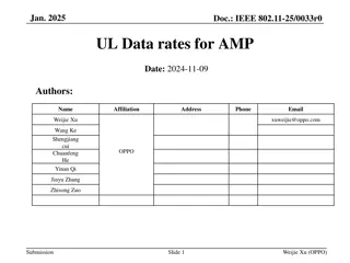
January 2024 doc.: IEEE 802.11-24/0075r0 Follow Up on AMP Link Budgets Date: 2024-01-15 Authors: Name Affiliations Address Phone Email Huawei, Shenzhen, China Wei Lin lin.linwei@huawei.com Huawei, Singapore Lei Huang Huawei, Shenzhen, China Bin Qian Huawei, Shenzhen, China Zhi Mao Huawei Huawei, Shenzhen, China Ying Li Huawei, Singapore Rojan Chitrakar Huawei, Singapore Shuqiao Chen Huawei, Shenzhen, China David Xun Yang Wei Lin et al, Huawei Submission Slide 1
January 2024 doc.: IEEE 802.11-24/0075r0 Recap of AMP Link Budget Computations [1] [2] The consideration of link budget computations were extensively discussed in [1] [2] [3] AMP-only device are assumed since AMP-assisted IoT device has similar coverage as the current Wi-Fi device In [1], three types of backscatter AMP IoT devices and one type of AMP IoT devices with active transmitters are assumed: Case 1: AMP IoT devices without power storage IoT Rx activation threshold of -20dBm Case 2: AMP IoT devices with power storage IoT Rx activation threshold of -30dBm Case 3: AMP IoT devices with power storage (Tx LNA Supported) IoT Rx activation threshold of -45dBm Case 4: AMP IoT devices with active transmitters IoT Rx activation threshold of -45dBm In [2], a category of close-range (~10cm) AMP backscattering use case is proposed for 2.4GHz AMP tag activation power: -20dBm, and reader dynamic range can be 30~50dB (assume 20dB antenna isolation) It should be noted that Friis equation is applied in both link budget evaluations [1], [2] Wei Lin et al, Huawei Submission Slide 2
January 2024 doc.: IEEE 802.11-24/0075r0 Recap of AMP Link Budget Computations [3] [3] extended the results of [1] from simple Friis equation to the 11n/ah defined channel models According to the defined channel models [2]-[4], shadowing fading shall be considered on either S1G (2~4 dB decreasing) or 2.4GHz (3~5 dB decreasing) channels Furthermore, breaking point at 10 meter distance shall be considered [2]-[4] Assume the sensitivities of the receivers have taken into account kTB, NF, and minimum SNR Sensitivity = 10xlog10(kTB) + 30 + NF + C/N Noise figure: the amount of noise power added by the electronic circuitry in the receiver to the thermal noise power from the input of the receiver. kTB: The total thermal noise power is a function of three quantities, 1) Boltzmann s constant k in Joules/ K, 2) temperature in Kelvin, and 3) the overall bandwidth of the channel selective filtering in the receiver. https://www.highfrequencyelectronics.com/index.php?option=com_content&view=article&id=553:receiver-sensitivity-and-equivalent-noise-bandwidth&catid=94:2014-06-june-articles&Itemid=189 Wei Lin et al, Huawei Submission Slide 3
January 2024 doc.: IEEE 802.11-24/0075r0 Overview of Backscatter Link Budget Calculation (1/2) In [7], link budgets of Backscatter IoT were extensively studied, and BackCom systems were categorized into three configurations - (a) MoBC (Monostatic BackCom): a reader and a tag - (b) BiBC (Bistatic BackCom): a separate dedicated RF emitter and reader - (c) AmBC (Ambient BackCom): utilize existing ambient RF emitters - - - LTdenotes the total losses in dB at the emitter, i.e., feeder loss, circuit loss (or any other loss) Xfdenotes the polarization mismatches of the forward link in dB. [7] D. Galappaththige, F. Rezaei, C. Tellambura, S. P. Herath, Link Budget Analysis for Backscatter-Based Passive IoT, IEEE Access, vol. 10, pp. 128890-128922, 2022. Wei Lin et al, Huawei Submission Slide 4
January 2024 doc.: IEEE 802.11-24/0075r0 Overview of Backscatter Link Budget Calculation (2/2) In [7], link budgets of Backscatter IoT were extensively studied, and BackCom systems were categorized into three configurations - (a) MoBC (Monostatic BackCom): a reader and a tag - - (b) BiBC (Bistatic BackCom): a separate dedicated RF emitter and reader - (c) AmBC (Ambient BackCom): utilize existing ambient RF emitters [1] [3] where P0tagand P0rare, respectively, the tag activation threshold and the reader sensitivity in dBm. - - - - LTdenotes the total losses in dB at the emitter, i.e., feeder loss, circuit loss (or any other loss) Xfdenotes the polarization mismatches of the forward link in dB. represents the on-object penalty gain of the antenna of tag, discounting any loss factors internal to tag circuit M is the modulation factor in dB, and F0 denotes the overall fade margin in dB. [7] D. Galappaththige, F. Rezaei, C. Tellambura, S. P. Herath, Link Budget Analysis for Backscatter-Based Passive IoT, IEEE Access, vol. 10, pp. 128890-128922, 2022. Wei Lin et al, Huawei Submission Slide 5
January 2024 doc.: IEEE 802.11-24/0075r0 Further Discussion on Link Budgets of AMP Devices Based on the discussion, to accurately calculate the link budgets of AMP devices, types or configurations of AMP devices should be clarified Type A: AMP-assisted IoT devices has similar capability as current Wi-Fi devices Similar Coverage Type B: AMP IoT devices with active transmitters power & signal transmitting coverages are de-coupled Type C: Backscatter AMP IoT devices with configuration MoBC and BiBC Downlink link budget computations of Type-B and Type C-1 / C-2 are similar For uplink link budget computations, the above mentioned three types are different Type B: AMP IoT devices with active transmitters Tx LNA Supported Type C (MoBC): DL & UL coverages are coupled, Tag shall be activated in the first place, and reader shall have enough dynamic range (Tx and Rx signal isolation, 30~50dB in [2]) to operate transmitting and receiving simultaneously Type C (BiBC): DL & UL coverages are de-coupled, no full duplex operation required at the reader [7] D. Galappaththige, F. Rezaei, C. Tellambura, S. P. Herath, Link Budget Analysis for Backscatter-Based Passive IoT, IEEE Access, vol. 10, pp. 128890-128922, 2022. Wei Lin et al, Huawei Submission Slide 6
January 2024 doc.: IEEE 802.11-24/0075r0 Downlink Link Budgets of AMP Devices Downlink link budget computations of Type B and Type C are similar Type B: AMP IoT devices with active transmitters power & signal transmitting coverages are de-coupled Type C: Backscatter AMP IoT devices with configuration MoBC and BiBC Pr = Pt + Gt + Gr + 20log10( ) 20log10(4 d) (with Friis Equation) Type B Type C MoBC / BiBC Antenna gain of IoT device (dBi) 2 2 Minimum receiving power for IoT device (dBm) -45 2.4 GHz -20 2.4 GHz Frequency EIRP of AP (dBm) 27 20 27 20 Max. commun. distance from AP to IoT device (m) (Friis) 49.85 22.27 2.80 1.25 Max. commun. distance from AP to IoT device (m) (11n Channel D) 17.8 920 MHz 11.32 2 920 MHz 0.88 Frequency EIRP of AP (dBm) 30 30 Max. commun. distance from AP to IoT device (m) (Friis) 183.70 10.33 Max. commun. distance from AP to IoT device (m) (11ah Channel D Indoor) 40.2 8 Wei Lin et al, Huawei Submission Slide 7
January 2024 doc.: IEEE 802.11-24/0075r0 Uplink Link Budgets of AMP Devices For uplink link budget computations, the above mentioned three types are different Type B: AMP IoT devices with active transmitters power & signal transmitting coverages are de-coupled Type C (BiBC): Backscatter AMP IoT devices with configuration BiBC consider worst case (Just Activated) Pr = Pt + Gt + Gr + 20log10( ) 20log10(4 d) (with Friis Equation) Type B Type C (BiBC) (Worst Case) Antenna gains of IoT device / AP (dBi) 0 0 Receiver sensitivity of AP (dBm) -95 -95 Maximum transmission power of IoT device (dBm) -15 -20 Backscattering loss at IoT device (dB) / 2.4 GHz 5 2.4 GHz Frequency Max. commun. distance from IoT device to AP (m) (Friis) 99.47 31.45 Max. commun. distance from IoT device to AP (m) (11n Channel D) 27 920 MHz 13.8 920 MHz Frequency Max. commun. distance from IoT device to AP (m) (Friis) 259.49 82.05 Max. commun. distance from IoT device to AP (m) (11ah Channel D Indoor) 48.7 25.48 Wei Lin et al, Huawei Submission Slide 8
January 2024 doc.: IEEE 802.11-24/0075r0 Uplink Link Budgets of AMP Devices For uplink link budget computations, the above mentioned three types are different Type C (MoBC): DL & UL coverages are coupled, Tag shall be activated in the first place, and reader shall have enough dynamic range (Tx and Rx signal isolation, 30~50dB in [2]) to operate both transmitting and receiving DL: Pr = Pt + Gt(AP) + Gr(STA) + 20log10( ) 20log10(4 d) (with Friis Equation) UL: Pr = Pt + Gt(AP) + Gr(STA) + Gt(STA) + Gr(AP) + 2 (20log10( ) 20log10(4 d)) (with Friis Equation) The UL equation of MoBC doesn t take the tag activation power into account, thus has to be adjusted to consider both tag activation power and AP dynamic range Therefore, the UL coverage of Type C (MoBC) can t larger than that of maximum DL coverage Furthermore, the requirement on Tx and Rx signal isolation at the reader may further limit the UL coverage If the EIRP of AP is 30dBm as we assumed before, with 50dB dynamic range (optimistic case) [2], theRx sensitivity of AP shall be around -20dBm If we decrease the Rx sensitivity of AP to better receive the backscatter signal from Tag, the EIRP of AP shall be decreased as well due to limited dynamic range of AP, which reduces the DL coverage. Wei Lin et al, Huawei Submission Slide 9
January 2024 doc.: IEEE 802.11-24/0075r0 Uplink Link Budgets of AMP Devices For uplink link budget computations, the above mentioned three types are different Type C (MoBC): DL & UL coverages are coupled, Tag shall be activated in the first place, and reader shall have enough dynamic range (Tx and Rx signal isolation, 30~50dB in [2]) to operate both transmitting and receiving DL: Pr(STA) = Pt(AP) + Gt(AP) + Gr(STA) + 20log10( ) 20log10(4 d) (with Friis Equation) Adjusted Equations UL: Pr(AP) = Pt(STA) + Gr(STA) + Gr(AP) + 20log10( ) 20log10(4 d) LBC (with Friis Equation) D L Type C (MoBC) U L Type C (MoBC) DL: - - - Antenna gains of IoT device / AP (dBi) 2 Antenna gains of IoT device / AP (dBi) 2 Pt = 0 dBm Pr(STA) = -20 dBm Gr = Gt = 2 dBi Pt(AP) 0 Receiver sensitivity of AP (dBm) -50 Maximum transmission power of IoT device (dBm) -20 Pt(STA) (dBm) -20 Backscattering loss at IoT device (dB) / Backscattering loss at IoT device (dB) 6 UL: - - - - 2.4 GHz 2.4 GHz Frequency Frequency Pr = -50 dBm Pt(STA) = -20 dBm LBC = 6 dB Gt = Gr = 2 dBi Max. DL distance (m) (Friis) 0.157 Max. UL distance (m) (Friis) 0.250 Max. DL distance (m) (11n Channel D) 0.111 Max. UL distance (m) (11n Channel D) 0.175 920 MHz 920 MHz Frequency Frequency Max. DL distance (m) (Friis) 0.411 Max. UL distance (m) (Friis) 0.651 Max. DL distance (m) (11ah Channel D Indoor) 0.324 Max. UL distance (m) (11ah Channel D Indoor) 0.514 Wei Lin et al, Huawei Submission Slide 10
January 2024 doc.: IEEE 802.11-24/0075r0 Summary To accurately calculate the link budgets of AMP devices, types or configurations of AMP devices should be clarified Type A: AMP-assisted IoT devices has similar capability as current Wi-Fi devices Similar Coverage Type B: AMP IoT devices with active transmitters power & signal transmitting coverages are de-coupled Type C: Backscatter AMP IoT devices with configuration MoBC and BiBC It can be observed that, there are significant DL and UL coverage imbalances Uplink coverages are larger than downlink coverages for Type-B, Type C devices under BiBC configurations For Type C devices under MoBC configuration, the UL coverage is at the level of tens of centimeters Uplink coverages are smaller than downlink coverages for Type C devices under MoBC configuration mainly due to the limited dynamic range (isolation) of AP/Reader Wei Lin et al, Huawei Submission Slide 11
January 2024 doc.: IEEE 802.11-24/0075r0 Thank You Wei Lin et al, Huawei Submission Slide 12
January 2024 doc.: IEEE 802.11-24/0075r0 References [1] IEEE 802.11-23/1562r8, Draft Technical Report on support of AMP IoT devices in WLAN [2] IEEE 802.11-23/2038r1, Close-range AMP Backscattering in 2.4GHz [3] IEEE 802.11-23/2013r0, Discussions on AMP Link Budgets [4] IEEE 802.11-03/940r4, TGn Channel Models [5] IEEE 802.11-11/0968r3, TGah Channel Model Proposed Text [6] IEEE 802.11-15/0425r1, Corrections to TGah Channel Model [7] D. Galappaththige, F. Rezaei, C. Tellambura, S. P. Herath, Link Budget Analysis for Backscatter-Based Passive IoT, IEEE Access, vol. 10, pp. 128890-128922, 2022. Wei Lin et al, Huawei Submission Slide 13
January 2024 doc.: IEEE 802.11-24/0075r0 Recap of AMP Link Budget Computations in [1] The Link Budget Evaluations for Case1/2/3 at both Sub 1 GHz and 2.4GHz Backscatter Transmitters Wei Lin et al, Huawei Submission Slide 14
January 2024 doc.: IEEE 802.11-24/0075r0 Recap of AMP Link Budget Computations in [1] The Link Budget Evaluations for Case 4 at both Sub 1 GHz and 2.4GHz Active Transmitters Wei Lin et al, Huawei Submission Slide 15
January 2024 doc.: IEEE 802.11-24/0075r0 Recap of AMP Link Budget Computations in [3] Adjusted Link budgets with 11n channel D at 2.4 GHz Case 1 Case 2 Case 1 Case 3/4 Case 2 Case 4 Case 3 Wei Lin et al, Huawei Submission Slide 16
January 2024 doc.: IEEE 802.11-24/0075r0 Recap of AMP Link Budget Computations in [3] Adjusted Link budgets with 11n channel model at 2.4GHz Case 1 Case 2 Case 3 Case 4 2.4 2.4 2.4 2.4 Frequency (GHz) EIRP of AP (dBm) 27 27 27 30 Receiver sensitivity of AP (dBm) -95 (Note 1) -95 (Note 1) -95 -95 Antenna gain of IoT device (dBi) 2 2 2 2 Minimum receiving power for IoT device (dBm) -20 (Note 2) -30 (Note 2) -45 (Note 3) -45 (Note 3) Max. commun. distance from AP to IoT device (m) (Friis [1]) (Note 6) 2.8 8.87 49.85 49.85 Max. commun. distance from AP to IoT device (m) (11n Channel D) 2 6 17.8 17.8 Backscattering loss at IoT device (dB) 5 5 5 / Maximum transmission power of IoT device (dBm) / / / -15 (Note 5) Low Noise Amplifier factor (dB) 0 0 30 (Note 4) / Max. commun. distance from IoT device to AP (m) (Friis [1]) (Note 6) 39.60 12.52 70.42 99.47 Max. commun. distance from IoT device to AP (m) (11n Channel D) 16 8.8 21.9 27 *Notes: (1) (2) (3) (4) (5) (6) Reuse the receiver sensitivity of an 802.11 ah AP The minimum required signal power for an IoT device is -20dBm when the IoT device can t store power itself. It can be -30dBm when the IoT device has the capability of power storage. -45 dBm is assumed as the sensitivity of ultra-low power receiver. LNA with 30 dBm gain is assumed to boost the backscattering signal, it can have ultra-low power consumption. Ultra-low power active transmitter is assumed. Distances calculated with Friis Equation in [1] Wei Lin et al, Huawei Submission Slide 17
January 2024 doc.: IEEE 802.11-24/0075r0 Recap of AMP Link Budget Computations in [3] Adjusted Link budgets with 11ah (indoor) channel D at sub 1GHz Case 1 Case 2 Case 3/4 Case 1 Case 2 Case 3 Case 4 Wei Lin et al, Huawei Submission Slide 18
January 2024 doc.: IEEE 802.11-24/0075r0 Recap of AMP Link Budget Computations in [3] Adjusted Link budgets with 11ah channel model at Sub-1GHz Case 1 Case 2 Case 3 Case 4 920 920 920 920 Frequency (MHz) EIRP of AP (dBm) 30 30 30 30 Receiver sensitivity of AP (dBm) -95 (Note 1) -95 (Note 1) -95 -95 Antenna gain of IoT device (dBi) 2 2 2 2 Minimum receiving power for IoT device (dBm) -20 (Note 2) -30 (Note 2) -45 (Note 3) -45 (Note 3) Max. commun. distance from AP to IoT device (m) (Friis [1]) (Note 6) 10.33 32.67 183.71 183.71 Max. commun. distance from AP to IoT device (m) (11ah Channel D Indoor) 8 15 40.2 40.2 Backscattering loss at IoT device (dB) 5 5 5 / Maximum transmission power of IoT device (dBm) / / / -15 (Note 5) Low Noise Amplifier factor (dB) 0 0 30 (Note 4) / Max. commun. distance from IoT device to AP (m) (Friis [1]) (Note 6) 103.31 32.67 183.71 259.49 Max. commun. distance from IoT device to AP (m) (11ah Channel D Indoor) 31 15 40.1 48.7 *Notes: (1) (2) (3) (4) (5) (6) Reuse the receiver sensitivity of an 802.11 ah AP The minimum required signal power for an IoT device is -20dBm when the IoT device can t store power itself. It can be -30dBm when the IoT device has the capability of power storage. -45 dBm is assumed as the sensitivity of ultra-low power receiver. LNA with 30 dBm gain is assumed to boost the backscattering signal, it can have ultra-low power consumption. Ultra-low power active transmitter is assumed. Distances calculated with Friis Equation in [1] Wei Lin et al, Huawei Submission Slide 19