Introduction to Finite State Machines in Engineering Design
Explore the concept of finite state machines in engineering design, with examples such as a dancing robot and a robot following a magnetic strip. Learn how state transitions control actions using sensors and without sensors in various scenarios. Discover how finite state machines model real-life processes, such as a student's academic progression, and grasp the basics of designing state diagrams for automation. Watch demonstrations and understand the implementation of simple state machines for different tasks.
Uploaded on | 0 Views
Download Presentation

Please find below an Image/Link to download the presentation.
The content on the website is provided AS IS for your information and personal use only. It may not be sold, licensed, or shared on other websites without obtaining consent from the author. If you encounter any issues during the download, it is possible that the publisher has removed the file from their server.
You are allowed to download the files provided on this website for personal or commercial use, subject to the condition that they are used lawfully. All files are the property of their respective owners.
The content on the website is provided AS IS for your information and personal use only. It may not be sold, licensed, or shared on other websites without obtaining consent from the author.
E N D
Presentation Transcript
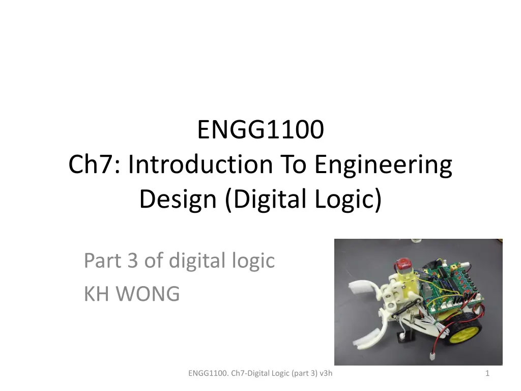
ENGG1100 Ch7: Introduction To Engineering Design (Digital Logic) Part 3 of digital logic KH WONG ENGG1100. Ch7-Digital Logic (part 3) v3h 1
Part3 Use a finite state machine to control the robot ENGG1100. Ch7-Digital Logic (part 3) v3h 2
Overview Understanding finite state machines 3a) A simple finite state machine (no sensor) E.g.: The dancing robot 3b) An finite state machine uses 2 sensors E.g. The robot that follows the magnetic strip 3c) A finite state machine uses 3 sensors E.g. Follow the magnetic strip, find the CAN and stop ENGG1100. Ch7-Digital Logic (part 3) v3h 3
Understanding finite state machines Example of a door State Transition Transition condition Entry action http://en.wikipedia.org/wiki/State_diagram ENGG1100. Ch7-Digital Logic (part 3) v3h 4
Example in life State of a student at CUHK Start: go to state 1 State 1=Year 1: entry action: register 12 courses Transition: go to state 2 after 1 year State 2=Year 2: entry action: register 12 courses Transition: go to state 3 after 1 year State 3=Year 3: entry action: register 12 courses Transition: go to state 4 after 1 year State 4=Year 4: entry action: register 8 courses and Final_year_project Transition: go to stop after 1 year Stop: Graduation ENGG1100. Ch7-Digital Logic (part 3) v3h 5
3a) The simple state machine (no transition condition ) The robot that dances with a pattern Forward 2 seconds, turn left 2 seconds and turn right 2 seconds, stops and repeat the pattern again Video demo: http://youtu.be/iyakbVyoafI ENGG1100. Ch7-Digital Logic (part 3) v3h 6
Simple finite state machine for (3a) : No sensor input (no transition condition) Start Entry actions Transition Output: LM1,LM2,RM1,RM2=1010 State1 Entry action: Move Forward Transition: After 2 seconds Transition: After 2 seconds State2 State4 E: Turn Left E:Stop After 2 seconds Output: LM1,LM2,RM1,RM2=0000 Output: LM1,LM2,RM1,RM2=0010 After 2 seconds State3 E:Turn Right Output: LM1,LM2,RM1,RM2=1000 Flow diagram Baisc form ENGG1100. Ch7-Digital Logic (part 3) v3h 7
Implementation of the finite state machine for (3a) Use of DELAY: DELAY_TIME=2000 motors(LM1,LM2,RM 1,RM2,SPEED,SPEE D,DELAY_TIME); Part of the sample source code is shown below: switch(state) { case STATE1: LM1=1;LM2=0;RM1=1;RM2=0;SPEED=200; //entry action DELAY_TIME=2000; // transition :delay 2 seconds motors(LM1,LM2,RM1,RM2,SPEED,SPEED,DELAY_TIME); state=STATE2; // next state will be state2 break; //end of the current state case STATE2: LM1=0;LM2=0;RM1=1;RM2=0;SPEED=200;DELAY_TIME=2000; // delay 2 seconds motors(LM1,LM2,RM1,RM2,SPEED,SPEED,DELAY_TIME); state=STATE3; //next state will be state3 break; //end of the current state // to be continued on next page Set motor to run forward with speed=200 System call to ask the motor to work Exercise: explain the meaning of state 2 ENGG1100. Ch7-Digital Logic (part 3) v3h 8
Continue from last page case STATE3: LM1=1;LM2=0;RM1=0;RM2=0;DELAY_TIME=2000; motors(LM1,LM2,RM1,RM2,SPEED,SPEED,DELAY_TIME); state=STATE4; break; case STATE4: LM1=0;LM2=0;RM1=0;RM2=0;SPEED=200;DELAY_TIME=2000; motors(LM1,LM2,RM1,RM2,SPEED,SPEED,DELAY_TIME); state=STATE1; break; default: //none of above will be forced to run state4 state=STATE4; break; } Exercises: explain the meaning of state 3 and 4 ENGG1100. Ch7-Digital Logic (part 3) v3h 9
3b) A finite state machine uses 2 sensors (with transition condition) E.g. The robot that follows the magnetic strip ENGG1100. Ch7-Digital Logic (part 3) v3h 10
Example in life (with transition condition : study hard) State of a student at CUHK Start go to state1 State 1=Year 1: entry action: register 12 courses Transition: if (study hard) promote to state2 (year2) else go back to state 1 State 2=Year 2: entry action: register 12 courses Transition: if (study hard) promote to state3 (year3) else go back to state 2 State 3=Year 3: entry action: register 12 courses Transition: if (study hard) promote to state4 (year4) else go back to state 3 State 4=Year 4: entry action: register 12 courses Transition: if (study hard) promote to stop(graduation) else back go to state4 Stop: Graduation ENGG1100. Ch7-Digital Logic (part 3) v3h 11
Demo 3b) An finite state machine uses 2 sensors The robot can follow the magnetic strip Video Demo: http://youtu.be/NWHjWrq_VoY Please refer to the program of demo 3c, Demo 3b and demo3c are using the same program. ENGG1100. Ch7-Digital Logic (part 3) v3h 12
3c) A finite state machine uses 3 sensors E.g. Follow the magnetic strip, find the CAN and stop Video Demo : http://youtu.be/JEQkuax7lKE The robot finds the CAN using the magnetic strip placed under the testing board and stops End point S1 Obstacle LM1,LM2 S3 S2 Start point RM1,RM2 ENGG1100. Ch7-Digital Logic (part 3) v3h 13
Finite state machine using 3 sensors (s1, s2, s3)with transition conditions for (3c) Flow diagram Basic form ENGG1100. Ch7-Digital Logic (part 3) v3h 14
Program 3c (S1, S2, S3 are used) S1, S2 for following the magnetic strip S3 for detecting the CAN The sample source code (program_segment3) is shown below: switch(state) { case STATE1: // forward for 1 second LM1=1;LM2=0;RM1=1;RM2=0; SPEED=200;DELAY_TIME=10; motors(LM1,LM2,RM1,RM2,SPEED,DELAY_TIME); // if ( S3()==1 && S2()==1 && S1()=0 ) state=STATE2; else if(S3()==1 && S2()==0 && S1()=1) state=STATE3; else if((S3==0) || (S3()==1 && S2()==0 && S1()=0)) state=STATE4; break; case STATE2: //robot turns left LM1=0;LM2=0;RM1=1;RM2=0;SPEED=200;DELAY_TIME=10; motors(LM1,LM2,RM1,RM2,SPEED,DELAY_TIME); // if ( S3()==1 && S2()==1 && S1()=1 ) state=STATE1; //back to state 1 else if(S3()==1 && S2()==0 && S1()=1) state=STATE3; else if((S3==0) || (S3()==1 && S2()==0 && S1()=0)) state=STATE4; break; ENGG1100. Ch7-Digital Logic (part 3) v3h Move forward for 1 second If S3=0, a CAN is detected, next state is state4 Robot Deviated right, goto state 2 Robot Deviated left goto state 3 15
case STATE3: //robot turns right LM1=1;LM2=0;RM1=0;RM2=0; SPEED=200;DELAY_TIME=10; motors(LM1,LM2,RM1,RM2,SPEED,DELAY_TIME); // if ( S3()==1 && S2()==1 && S1()=1 ) state=STATE1; else if(S3()==1 && S2()==1 && S1()=0) state=STATE2; else if((S3==0) || (S3()==1 && S2()==0 && S1()=0)) state=STATE4; break; case STATE4: //stop LM1=0;LM2=0;RM1=0;RM2=0; SPEED=200;DELAY_TIME=10; motors(LM1,LM2,RM1,RM2,SPEED,DELAY_TIME); break; default: //none of above states state=STATE4; LM1=0;LM2=0;RM1=0;RM2=0; SPEED=200;DELAY_TIME=10; motors(LM1,LM2,RM1,RM2,SPEED,DELAY_TIME); break; } ENGG1100. Ch7-Digital Logic (part 3) v3h If S3=0,a CAN is detected Next state is state4 State4 is the stop state, the robot stops 16
Summary In digital logic part 1,2 & 3, we learned What is digital logic Digital logic operations represented by Digital logic formula method Truth table method Their implementation methods using programs Final state machines Theory and implementations Use the above to control a robot for specific tasks ENGG1100. Ch7-Digital Logic (part 3) v3h 17
End ENGG1100. Ch7-Digital Logic (part 3) v3h 18

