Introduction to Operational Amplifiers in Electronic Circuits

An electronic circuit is a group of components connected for a specific purpose. Integrated Circuits (ICs) offer advantages like compact size, reduced cost, increased reliability, and improved operating speeds. Analog ICs, such as Linear ICs, play a crucial role in electronic systems.

Download Presentation

Please find below an Image/Link to download the presentation.
The content on the website is provided AS IS for your information and personal use only. It may not be sold, licensed, or shared on other websites without obtaining consent from the author.If you encounter any issues during the download, it is possible that the publisher has removed the file from their server.
You are allowed to download the files provided on this website for personal or commercial use, subject to the condition that they are used lawfully. All files are the property of their respective owners.
The content on the website is provided AS IS for your information and personal use only. It may not be sold, licensed, or shared on other websites without obtaining consent from the author.
E N D
Presentation Transcript
M.S.P. Mandals Deogiri College,Aurangabad Department of Instrumentation Practice Class :- B. Sc. S. Y. (sem lll) Course :- Instrumentation Vl Chapter:-Introduction to Operational amplifiers Part :- 1 Mrs. S.B.Patil
Introduction to Operational amplifiers: Anelectronic circuit is a group of electronic components connected for a specific purpose. A simple electronic circuit can be designed easily because it requires few discrete electronic components and connections. However, designing a complex electronic circuit is difficult, as it requires more number of discrete electronic components and their connections. It is also time taking to build such complex circuits and their reliability is also less. These difficulties can be overcome with Integrated Circuits. Integrated Circuit (IC) If multiple electronic components are interconnected on a single chip of semiconductor material, then that chip is called as an Integrated Circuit (IC). It consists of both active and passive components. This chapter discusses the advantages and types of ICs.
Advantages of Integrated Circuits Integrated circuits offer many advantages. They are discussed below Compact size For a given functionality, you can obtain a circuit of smaller size using ICs, compared to that built using a discrete circuit. Lesser weight A circuit built with ICs weighs lesser when compared to the weight of a discrete circuit that is used for implementing the same function of IC. using ICs, compared to that built using a discrete circuit. Low power consumption ICs consume lower power than a traditional circuit, because of their smaller size and construction.
Reduced cost ICs are available at much reduced cost than discrete circuits because of their fabrication technologies and usage of lesser material than discrete circuits. Increased reliability Since they employ lesser connections, ICs offer increased reliability compared to digital circuits. Improved operating speeds ICs operate at improved speeds because of their switching speeds and lesser power consumption.
Types of Integrated Circuits Integrated circuits are of two types Analog Integrated Circuits and Digital Integrated Circuits. Analog Integrated Circuits:- Integrated circuits that operate over an entire range of continuous values of the signal amplitude are called as Analog Integrated Circuits. These are further classified into the two types as discussed here Linear Integrated Circuits An analog IC is said to be Linear, if there exists a linear relation between its voltage and current. IC 741, an 8-pin Dual In-line Package (DIP)op-amp, is an example of Linear IC.
Radio Frequency Integrated Circuits An analog IC is said to be Non-Linear, if there exists a non-linear relation between its voltage and current. A Non-Linear IC is also called as Radio Frequency IC. Digital Integrated Circuits:- If the integrated circuits operate only at a few pre-defined levels instead of operating for an entire range of continuous values of the signal amplitude, then those are called as Digital Integrated Circuits. Operational Amplifier, also called as an Op-Amp, is an integrated circuit, which can be used to perform various linear, non-linear, and mathematical operations. An op-amp is a direct coupled high gain amplifier. You can operate op-amp both with AC and DC signals.
An operational amplifier, also called as an op-amp or op amp, is an integrated circuit primarily designed for performing analogue computations. It has a very high voltage gain, typically of the order of 104 (100dB). Although they are specially designed for performing operations like addition, differentiation etc., by using external components like resistors and capacitors to create a required feedback mechanism, it can also be used as an amplifier and for many other functions like filters, comparators etc. subtraction, integration,
IC 741 Op Amp (Operational Amplifier) The 741 Op Amp IC is a monolithic integrated circuit, comprising of a general purpose Operational Amplifier. It was first manufactured by Fairchild semiconductors in the year 1963. The number 741 indicates that this operational amplifier IC has 7 functional pins, 4 pins capable of taking input and 1 output pin. IC 741 Op Amp can provide high voltage gain and can be operated over a wide range of voltages, which makes it the best choice for use in integrators, summing amplifiers and general feedback applications. It also features short circuit protection and internal frequency compensation circuits built in it. This Op-amp IC comes in the following form factors: 8 Pin DIP Package TO5-8 Metal can package 8 Pin SOIC
Now lets take a look at the functions of different pins of 741 IC:- 1) Pin4 & Pin7 (Power Supply): Pin7 is the positive voltage supply terminal and Pin4 is the negative voltage supply terminal. The 741 IC draws in power for its operation from these pins. The voltage between these two pins can be anywhere between 5V and 18V. 2) Pin6 (Output): This is the output pin of IC 741. The voltage at this pin depends on the signals at the input pins and the feedback mechanism used. If the output is said to be high, it means that voltage at the output is equal to positive supply voltage. Similarly, if the output is said to be low, it means that voltage at the output is equal to negative supply voltage.
3) Pin2 & Pin3 (Input): These are input pins for the IC. Pin2 is the inverting input and Pin3 is the non-inverting input. If the voltage at Pin2 is greater than the voltage at Pin3, i.e., the voltage at inverting input is higher, the output signal stays low. Similarly, if the voltage at Pin3 is greater than the voltage at Pin2, i.e., the voltage at non-inverting input is high, the output goes high. 4) Pin1 & Pin5 (Offset Null): Because of high gain provided by 741 Op- Amp, even slight differences in voltages at the inverting and non-inverting inputs, caused due to irregularities in manufacturing process or external disturbances, can influence the output. To nullify this effect, an offset voltage can be applied at pin1 and pin5, and is usually done using a potentiometer. 5) Pin8 (N/C): This pin is not connected to any circuit inside 741 IC. It s just a dummy lead used to fill the void space in standard 8 pin packages.
What is an op -amplifier The operational amplifier or op-amp is a circuit of components integrated into one chip. A typical op-amp is powered by two dc voltages and has one inverting(-) input, one non-inverting input (+) and one output. Op-amps are used to model the basic mathematical operations ; addition, subtraction, integration and differentiation in electronic analog computers.
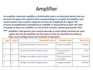
Low cost integrating circuit consisting of: Transistors Resistors Capacitors Able to amplify a signal due to an external power supply Name derives from its use to perform operations on a signal.
Operation amplifier has two inputs:- One is called the inverting input and is marked with a - sign . The other is the non-inverting input and this is marked with a "+" sign. The op amp is basically a differential amplifier because the output is proportional to the difference in voltage between the two inputs. Non-inverting input: The operational amplifier non-inverting input is marked by a "+" sign . It is found that a positive voltage applied to the non-inverting input will produce a positive swing at the output. If a changing waveform, such as a sine wave is applied to the non- inverting input, then it will appear in the same sense at the output. It has not been inverted.
By applying an input signal to the non-inverting input and negative feedback to the investing input, it is possible to design a circuit that does not invert the sense of the input signal.
Inverting input: The operational amplifier inverting input is marked by a "-" sign on the circuit diagram. A positive voltage applied to the inverting input will produce a negative swing at the output. Thus a sine wave applied to the inverting input, will appear inverted at the output. By applying the signal and negative feedback to the inverting input of an operational amplifier, it is possible to design a circuit where the output signal is the inverse of the input.
If the same voltage is applied to both inputs together then there should be no change at the output. In fact the output is proportional to the difference between the inverting and non- inverting inputs. It is for this reason that these amplifiers are often called differential amplifiers.


")


 Pin2 & Pin3 (Input): These are input pins for the IC.")