James Webb Space Telescope Mirror Model Assembly Guide
Discover how to create a detailed James Webb Space Telescope mirror model using a 3D printer and various materials. Follow step-by-step instructions and learn about the STL files needed for assembly.

Download Presentation

Please find below an Image/Link to download the presentation.
The content on the website is provided AS IS for your information and personal use only. It may not be sold, licensed, or shared on other websites without obtaining consent from the author. If you encounter any issues during the download, it is possible that the publisher has removed the file from their server.
You are allowed to download the files provided on this website for personal or commercial use, subject to the condition that they are used lawfully. All files are the property of their respective owners.
The content on the website is provided AS IS for your information and personal use only. It may not be sold, licensed, or shared on other websites without obtaining consent from the author.
E N D
Presentation Transcript
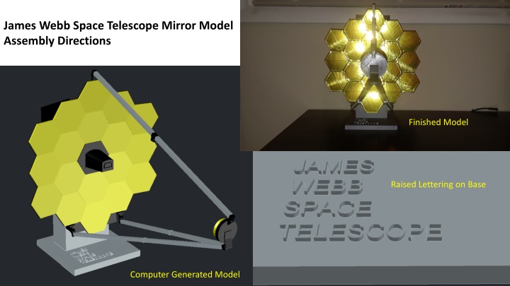
James Webb Space Telescope Mirror Model Assembly Directions Finished Model Raised Lettering on Base Computer Generated Model
Materials Used: Prusa i3 MK3S 3D printer PLA filament (1.75 mm) Spray paint black and metallic silver (or those colors in PLA filament) Gold Mylar tape or gold spray paint, the Mylar adds a shiny realism Wooden dowels (2) 12 in. long, 1/16 in. diameter (for secondary mirror rods to make them sturdy) Aluminum tubing 12 in. long, 3/32 in. diameter, cut into two 5 1/8 in. long pieces (for back hinges) Glue for assembly, I used Gorilla glue but any brand should suffice Acetone to bring back the shine after gluing the pieces with Mylar, the glue vapors show fingerprints (like a CSI scene), only a gentle wipe is needed Patience and Time!
STL files: Total Needed Back bottom (1) Back hinge cap (4) Back hinge (8) Back top (1) Base rod (1) Base (1) Detector (1) Hinge pc 1 (1) Hinge pc 2 (2) Hinge rod short (5) Mirror panel (18) Mirror support (1-4deg) (2) Mirror support (2-4deg) (6) Mirror support (11) Rod (7.5 with hole) (2) Rod (8 with hole) (2) Rod (8) (2) Rod cap joint (2) Rod cap (2) Rod hinge (4) Sec. mirror (1) SM base (1) STL files: Total Needed SM rod cap piece (1) SM rod caps (1) SMR left hinge (1) SMR right hinge (1) SMR top hinge (1) 11 in. wide 14.75 in. tall 22.5 in. tall (when folded) Total files = 27 STL files Total pieces printed = 83 pieces Printing scale = 2540% scale Model dimensions once completed = 20 in. deep
Sides folded back, rods folded up All the pieces made before final assembly
Note: The mirror support (1-4deg) and mirror support (2-4deg) have 4 degree slants designed to maintain curvature, mark the pieces so you don t forget which is which. When you bring up the STL file, they are on the front and back, respectively (2-4deg) slant on front and back of pieces (1-4deg) slant on front of piece
The yellow support panels are only to show where the mirror support (1-4deg) pieces are placed during assembly The red support panels are only to show where the mirror support (2-4deg) pieces are placed during assembly This design allows for a natural curvature of the mirror, all pieces have a 4 degree slant in this configuration which goes up 4 additional degrees as each piece is added
Glue the rows of support panels individually, then tape the middle three rows to make gluing them easier: DO NOT GLUE THE OUTER PANELS TO THE MIDDLE THREE, they will swing back with hinges Insert wooden dowel between the 7.5 and 8 in rods, then slide the rod cap joint over the seem, gluing the pieces together Remove tape once glue has dried, then glue where tape was, smooth out glue to not lump up Assembled rods with secondary mirror and hinges Use the curved back surface to glue the support panels together, this will help maintain the mirror curvature
Glue assembled back hinges once support panels are glued together, use tape to hold sides in place until hinges dry 1 inch 1 inch Back hinges 2 inch Crimp the rod with pliers around the hinges to help prevent slippage 5 1/8 inch Cut Rod + 4 back hinges + 2 back hinge caps
Rod hinge and hinge rod SMR Top Hinge Glue the SMR top hinge to support panel
Rod hinge and hinge rod Sec. mirror (attach Mylar or paint gold, then glue to base) SM base SM rod cap piece (glue to base) SM rod caps (glue to rod cap piece)
The SMR left and right hinges will fit over the support panels SMR Right Hinge Rod hinge and hinge rod
The SMR left and right hinges will fit over the support panels SMR Left Hinge Rod hinge and hinge rod
Rod (8) x2 Rod (8 with hole) x2 Rod (7.5 with hole) x2 Rod cap joint x2
Rod cap x2 Hinge pc 2 x2 Hinge pc 1 + Hinge rod Insert the rod into the hinge pieces Before you glue to the rod caps, this will make this step easier
Glue the assembled support panel structure, with rod assembly, centered onto the back pieces before gluing the detector and mirror panels, (attach gold mylar or paint gold BEFORE attaching mirror panels)
Insert the base rod into the base, then lower the mirror assembly onto them both and glue them all together
The finished model should like this, the sides should fold back and secondary mirror should fold up to mimic the configuration during storage for flight Appreciate your hard work at this point and enjoy your new model!


 and mirror support")


 x2")


![get⚡[PDF]❤ The Hubble Space Telescope: From Concept to Success (Springer Praxis](/thumb/21514/get-pdf-the-hubble-space-telescope-from-concept-to-success-springer-praxis.jpg)