Long Range Extension of 802.15.4-2020 OFDM PHY Proposal
Explore a new long-range extension proposal for the SUN 802.15.4 OFDM PHY with re-use of existing technology. The document outlines modifications needed in OFDM modulators, including DSSS and DBPSK usage. Discover how this proposal enhances signal detection in low SNR conditions and encapsulates binary information effectively. This submission serves as a basis for discussion within the IEEE P802.15 community.

Download Presentation

Please find below an Image/Link to download the presentation.
The content on the website is provided AS IS for your information and personal use only. It may not be sold, licensed, or shared on other websites without obtaining consent from the author. If you encounter any issues during the download, it is possible that the publisher has removed the file from their server.
You are allowed to download the files provided on this website for personal or commercial use, subject to the condition that they are used lawfully. All files are the property of their respective owners.
The content on the website is provided AS IS for your information and personal use only. It may not be sold, licensed, or shared on other websites without obtaining consent from the author.
E N D
Presentation Transcript
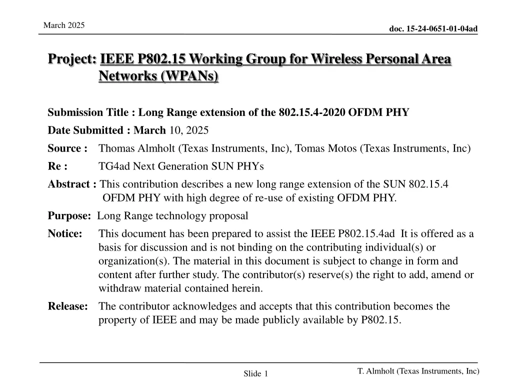
March 2025 doc. 15-24-0651-01-04ad Project: IEEE P802.15 Working Group for Wireless Personal Area Networks (WPANs) Submission Title : Long Range extension of the 802.15.4-2020 OFDM PHY Date Submitted : March 10, 2025 Source : Thomas Almholt (Texas Instruments, Inc), Tomas Motos (Texas Instruments, Inc) Re : TG4ad Next Generation SUN PHYs Abstract : This contribution describes a new long range extension of the SUN 802.15.4 OFDM PHY with high degree of re-use of existing OFDM PHY. Purpose: Long Range technology proposal Notice: This document has been prepared to assist the IEEE P802.15.4ad It is offered as a basis for discussion and is not binding on the contributing individual(s) or organization(s). The material in this document is subject to change in form and content after further study. The contributor(s) reserve(s) the right to add, amend or withdraw material contained herein. Release: The contributor acknowledges and accepts that this contribution becomes the property of IEEE and may be made publicly available by P802.15. T. Almholt (Texas Instruments, Inc) Slide1
March 2025 doc. 15-24-0651-01-04ad Submission Title : Long Range extension of the 802.15.4-2020 OFDM PHY Date Submitted : Initial filing Feb 11, 2024, Revised March 10, 2025 Source : Thomas Almholt (Texas Instruments, Inc), Tomas Motos (Texas Instruments, Inc) Re : TG4ad Next Generation SUN PHYs Abstract : This contribution describes a new long range extension of the herein. Release: T. Almholt (Texas Instruments, Inc) Slide2
March 2025 doc. 15-24-0651-01-04ad Agenda SUN OFDM VLR as SC-FDMA extension from SUN OFDM Packet Structure Channel Access Mechanism (STF) Interleaver DBPSK Modulation Kernel OFDM Windowing LCG Linear Congruential Generator Channel Model Simulations Network Capacity Simulations T. Almholt (Texas Instruments, Inc) Slide3
March 2025 doc. 15-24-0651-01-04ad SUN OFDM VLR as SC-FDMA There are only three blocks that need to be modified in an OFDM modulator to account for a new scheme DSSS (Direct Sequence Spread Spreading) blocks takes information bits coming from the Interleaver and expands them into series of chips The Chips to Symbol is restricted to BPSK (Binary Phase Shift Keying), using a Differential Encoding Out of the N possible sub-carriers of OFDM only a single carrier is used T. Almholt (Texas Instruments, Inc) Slide4
March 2025 doc. 15-24-0651-01-04ad SUN OFDM VLR as SC-FDMA 1. The use of DSSS creates additional redundancy to the transmitted information sequence to allow detection in lower SNR conditions (in the presence of more noise energy, or lower signal energy) 2. The use of DBPSK (differential BPSK) to encode the binary information into symbols, on a pair-by-pair basis. Each of the OFDM symbols is sub divided into two sub-symbols transmitted on the same sub-carrier. This scheme allows a local view of the incoming symbols on the same sub- carrier. This scheme effectively removes the need for precise channel equalization. 3. A single subcarrier is employed for each of the OFDM symbol. This effectively modifies OFDM into a system with N=1 and allows a Peak-to-Average-Power Ratio (PAPR) of around 1 dB 4. Additional linear filtering across OFDM symbols reduces the Adjacent Channel Power (ACP) and simplifies upsampling of the baseband signal. T. Almholt (Texas Instruments, Inc)
March 2025 doc. 15-24-0651-01-04ad SUN OFDM VLR as SC-FDMA T. Almholt (Texas Instruments, Inc)
March 2025 doc. 15-24-0651-01-04ad SUN OFDM VLR Packet Structure The STF is 80 bits encoded to 160 chips, on a single sub-carrier The LTF is 26 bits encoded to 52 chips, using the same hopping sequence as the rest of the packet The PHR contains 24 information bits, 48 coded bits, interleaved and then spread to 288 chips, using the same hopping sequence as the rest of the packet The PSDU contains n information bits, 2*n coded bits, interleaved and then spread to n*DSSS*2 chips T. Almholt (Texas Instruments, Inc)
March 2025 doc. 15-24-0651-01-04ad Channel Access Mechanism Nodes synchronize on a specific sub-carrierthat must be known in advance (the meeting point ) A subset of the sub-carriers is employed per network, so multiple networks can easily coexist by employing different subsets Transmitting devices can randomly select between the N valid synchronization sub-carriers for each of their transmissions Receiving nodes shall be able to listen to any of these sub-carriers. Typically, this is achieved by an N-node receiver configuration (but N can be 1 for simpler network topographies). This scheme allows flexibility and scalability to network configurations and enables SUN OFDM VLR to be deployed with different network parameters 1-to-many : single collector node, many end-nods N-to-many : N-collector node, many end-nodes The general concept is that there is a subset of sub-carriers per network (out of the total active subcarriers) that can be used for STF. This is like the Advertising Channel concept (3 out of 40 channels) employed by Bluetooth LE devices T. Almholt (Texas Instruments, Inc) 8
March 2025 doc. 15-24-0651-01-04ad Interleaver SUN OFDM VLR packets are byte oriented In order to avoid additional padding requirements and reduce HW complexity, the interleaver size is adapted to this packet structure. Every incoming 8 bits are transformed into 16 coded bits by the FEC convolutional encoder Those 16 coded bits are then interleaved on a 4x4 interleaver engine, same as the existing configuration in SUN FSK T. Almholt (Texas Instruments, Inc) 9
March 2025 doc. 15-24-0651-01-04ad DBPSK Modulation Kernel BPSK symbols are always transmitted in pairs on the same sub-carrier The difference of the phase between the first symbol and the second symbol encodes the information At the receiver, the local phase (per sub-carrier) ?? is irrelevant, as the Soft Metric function does not depend on it. This is a key aspect of the design. ?0?= ?????? ?????? ?1?= ?????? ????(?+??) ? ??= ?? ? ?+??= ?? ?0?= ???0 ???0 ?1?= ???0 ???? 2 ??0?= ??????.?? ??1?= ?? ????.?? 2 Transmitted pair i Received pair i Received soft metric i T. Almholt (Texas Instruments, Inc)
March 2025 doc. 15-24-0651-01-04ad DBPSK Properties + Unknown phase (per channel) is cancelled out + Frequency Offset Estimation Requirements are significantly reduced + Only inter-symbol frequency offset remnant is meaningful (<SymDur) + XTAL Drift Requirements significantly reduced + Timing Errors estimation requirements significantly reduced + No strict symbol synchronization nor tracking is required + Allows shorter STF and LTF sequences + Equalization and tracking over time requirements significantly reduced + Each sub-carrier can be considered as an independent narrow-band DBPSK channel + As every subchannel is demodulated independently (DBPSK) the amplitude/phase variations do not affect the overall demodulation across sub-channels + Effectively SUN OFDM VLR operates as demodulating independent subchannels of 10 kHz/20kHz/40kHz/80 KHz The general message here is that due to the time-frequency sparsity of the transmitted signal, only differential encoding is feasible to allow low-complexity, low-overall-system-cost, battery powered operations T. Almholt (Texas Instruments, Inc)
March 2025 doc. 15-24-0651-01-04ad BPSK-with-pilot-tones issues (1/3) 9 12 2 11 14 4 13 3 6 5 7 10 9 12 2 11 14 4 13 3 6 5 7 10 Each of sub-carrier is visited evenly and only once every N_AT (number of active tones) (Example, N_AT = 12) Corollary: the period between each of the sub-carriers is equal to the number of active sub-carrier This also applies to the distances between the LTF, PHR and PSDU If pilot tones are inserted on a 2 pilot tones per 6 data symbols (1 every 3), the distance between pilot tones on average is (3+1)*N_AT symbols (assuming that pilot tones are distributed so that they visit all sub-carriers over time) For SymDur = 120 us and N_AT = 104, the distance between a pilot tone on the same sub-carrier is 49.2 ms!! The maximum remnant frequency offset error for the phase rotation to be within 45 degrees from the previous symbol is: Even if a receiver could obtain this resolution for the measurement, the XTAL stability requirements (Allan Variance) moves to the parts-per- billion ? 4= 2?????? 1 ???? = 2.5 Hz 8?= ???? T. Almholt (Texas Instruments, Inc)
March 2025 doc. 15-24-0651-01-04ad BPSK-with-pilot-tones issues (2/3) 9 12 2 11 14 4 13 3 6 5 7 10 9 12 2 11 14 4 13 3 6 5 7 10 Symbols per sub-channel are visited every N_AT. Timing error becomes a phase error. Timing drift for 20 ppm XTALs: 40ppm*N_AT*SymDur = 0.5 us -> linear phase error for each of the sub- carriers Example: for sub-carrier +52 (52 cyles per 96 us) -> 0.5 us corresponds to over pi/2 rotation, just due to timing offset errors Supporting 20 ppm XTALs becomes very challenging due to the scarcity and the time separation between pilots T. Almholt (Texas Instruments, Inc)
March 2025 doc. 15-24-0651-01-04ad BPSK-with-pilot-tones issues (3/3) A coherent modulation that requires to equalize each of the sub-channels and operates at ~5 dB lower SNR would require a substantially longer STF and LTF sequences. Both STF and LTF shall be able to allow very strict frequency offset, symbol timing errors recovery. We are assuming at least x4 the duration for the STF and x8 the duration for the LTF (four visits to each sub-carrier) For short duration packets, this investment is significant. DBPSK has shorter packet lengths than BPSK with pilots up to ~35 PDU sizes DSSS=2 SymDur=120 us Even for PDUs of 50 bytes, the difference between the two is only +10% of penalty for DBPSK T. Almholt (Texas Instruments, Inc)
March 2025 doc. 15-24-0651-01-04ad DBPSK summary ?0?= ?????? ?????? ?1?= ?????? ????(?+??) ? ??= ?? ? ?+??= ?? 2 ??0?= ??????.?? ??1?= ?? ????.?? 2 + Differential BPSK is the only modulation kernel that can effectively be used on the sparse time/frequency resources of SUN OFDM VLR + BPSK modulations bring extreme requirements of frequency offset estimation, timing offset tracking, XTAL Allan Variance in the part-per-billion range + Other competing chirp-based technologies are also affected by these impairments and never achieve the datasheet sensitivity or AWGN sensitivity in the real world + When using a DBPSK kernel each sub-carrier can be demodulated independently without any need for channel equalization: frequency selective fading becomes flat-fading for each of the sub-carriers and phase and time drift are solved locally at the symbol level + DBPSK still meets the sensitivity requirements (< -120 dBm) T. Almholt (Texas Instruments, Inc)
March 2025 doc. 15-24-0651-01-04ad XTAL requirements According to the Open Metering Standard Document Annex Q to Volume 2 Primary Communication Issue 5.0.1 (release 2023-12) Q.F.1 Common Causes and Techniques to Reduce Centre Frequency Drift A common cause of centre frequency drift in the endpoint transmitter stems from impairments on the RF reference clock. Instability on the RF reference clock voltage supply, start-up characteristics of the RF reference clock and heat transfer from transceiver to RF reference clock are some of the most common impairments. [ ] Even small fluctuations of the voltage will cause noticeably frequency shifts which will translate into centre frequency drift on the transmitted signals. It is therefore important to use a hardware design which insures a stable voltage supply at all times. T. Almholt (Texas Instruments, Inc)
March 2025 doc. 15-24-0651-01-04ad OFDM Windowing SUN OFDM does not currently specify any windowing between symbols We propose that this is changed for the next revision of the SUN OFDM specification. This change would also carry over to SUN OFDM VLR A linear ramp for the first half of the CP is sufficient CP Duration Symbol Duration Base Symbol Duration 96 us 48 us 24 us 12 us 24 us 12 us 6 us 3 us 120 us 60 us 30 us 15 us T. Almholt (Texas Instruments, Inc) Slide17
March 2025 doc. 15-24-0651-01-04ad Linear Congruential Generator https://en.wikipedia.org/wiki/Linear_congruential_generator https://en.wikipedia.org/wiki/Linear_congruential_generator is an iterative algorithm that yields a sequence of pseudo-randomized numbers General case: ??+1= ((??? +?) ??? ?) Additionally, numbers are re-rolled if falling outside the number of active tones defined by each of the operating modes or if the number is the DC tone For SUN OFDM VLR, we can select some specific values for a, c and m = 2*N_DFT Index 0 1 2 3 4 5 6 7 a 17 29 37 41 53 61 73 89 Index 0 1 2 3 4 5 6 7 8 9 c 3 5 7 11 13 17 19 23 29 31 Index 10 11 12 13 14 15 16 17 18 19 c 37 41 43 47 53 59 61 67 71 73 Index 20 21 22 23 24 25 26 27 28 29 c 79 83 89 97 101 103 107 109 113 127 T. Almholt (Texas Instruments, Inc) Slide18
March 2025 doc. 15-24-0651-01-04ad Linear Congruential Generator There are 8*30 = 240 different hopping sequences available Devices using different hopping sequences do not interfere with each other Even when using the same sequence, devices only interfere with each other if the sequences are perfectly aligned at the symbol level ??+1= ((??? +?) ??? ?) ??+1= ??+1 ????/2 Example, N_DFT = 32, N_AT = 26, A=17, C=83. Reroll when X[n] = N_DFT, X[n] < N_DFT-N_AT/2, X[n] > N_DFT+N_AT/2 17 7 10 12 21 11 14 25 15 18 5 20 29 19 22 9 24 4 23 26 13 3 6 28 8 27 17 7 10 12 21 11 14 25 15 18 5 20 29 19 22 9 24 4 23 26 13 3 6 28 8 27 Each sub-channel is visited only once per repetition The repetitions are always identical Each sub-channel is visited every N_AT symbols T. Almholt (Texas Instruments, Inc) Slide19
March 2025 doc. 15-24-0651-01-04ad Channel Model Simulations T. Almholt (Texas Instruments, Inc) 20
March 2025 doc. 15-24-0651-01-04ad Selected Modes T. Almholt (Texas Instruments, Inc)
March 2025 doc. 15-24-0651-01-04ad Channel Model for SUN OFDM VLR Channel Models AWGN LOS (ETSI TR 138 901 TDL-D DSdesired = 1000 ns) NLOS (ETSI TR 138 901 TDL-B DSdesired = 1000 ns) Matlab Models (nrTDLChannel) employed for channel generation Model randomized on a packet-per-packet basis 200 packets per signal level, 20 bytes per packet Theoretical NF = 0 dB Different implementations can displace the provided curves by their own NF Full model of the SUN OFDM VLR receiver Timing and Frequency Synchronization to the STF channel Hopping Patterns Interleaving DBPSK demodulation FEC T. Almholt (Texas Instruments, Inc)
March 2025 doc. 15-24-0651-01-04ad Example: O1, 1 MHz BW - 10kHz subcarriers (104 tones) simulation CRC OK Amplitude and Phases varies quickly and significantly (20 dB in amplitude, non-linear phase variations) between faded sub-channels (TDL-B) T. Almholt (Texas Instruments, Inc)
March 2025 doc. 15-24-0651-01-04ad Option 1 DSSS = 2 10 kHz subcarriers 2kbps AWGN (10 % PER) -128 dBm TDL-D (10% PER) -125.5 dBm TDL-B (10% PER) -122 dBm T. Almholt (Texas Instruments, Inc)
March 2025 doc. 15-24-0651-01-04ad Option 1 DSSS = 2 20 kHz subcarriers 4kbps AWGN (10 % PER) -125.5 dBm TDL-D (10% PER) -123 dBm TDL-B (10% PER) -119 dBm T. Almholt (Texas Instruments, Inc)
March 2025 doc. 15-24-0651-01-04ad Option 1 DSSS = 2 40 kHz subcarriers 8kbps AWGN (10 % PER) -124 dBm TDL-D (10% PER) -121 dBm TDL-B (10% PER) -117 dBm T. Almholt (Texas Instruments, Inc)
March 2025 doc. 15-24-0651-01-04ad Option 1 DSSS = 2 80 kHz subcarriers 16kbps AWGN (10 % PER) -122 dBm TDL-D (10% PER) -119 dBm TDL-B (10% PER) -114 dBm T. Almholt (Texas Instruments, Inc)
March 2025 doc. 15-24-0651-01-04ad Option 4 DSSS = 2 10 kHz subcarriers 2kbps AWGN (10 % PER) -129 dBm TDL-D (10% PER) -126.5 dBm TDL-B (10% PER) -122 dBm T. Almholt (Texas Instruments, Inc)
March 2025 doc. 15-24-0651-01-04ad Option 3 DSSS = 2 20 kHz subcarriers 4kbps AWGN (10 % PER) -127.5 dBm TDL-D (10% PER) -124.5 dBm TDL-B (10% PER) -119 dBm T. Almholt (Texas Instruments, Inc)
March 2025 doc. 15-24-0651-01-04ad Option 2 DSSS = 2 40 kHz subcarriers 8kbps AWGN (10 % PER) -125 dBm TDL-D (10% PER) -122 dBm TDL-B (10% PER) -117 dBm T. Almholt (Texas Instruments, Inc)
March 2025 doc. 15-24-0651-01-04ad Summary Table AWGN TDL-D (LOS) TDL-B (NLOS) O1 DSSS2 10 kHz 2 kbps -128 dBm -125.5 dBm -122 dBm O4 DSSS2 10 kHz 2 kbps -129 dBm -126.5 dBm -122 dBm O1 DSSS2 20 kHz 4 kbps -125.5 dBm -123 dBm -119 dBm O3 DSSS2 10 kHz 2 kbps -127.7 dBm -124.5 dBm -119 dBm O1 DSSS2 40 kHz 8 kbps -124 dBm -121 dBm -117 dBm O2 DSSS2 10 kHz 2 kbps -125 dBm -122 dBm -117 dBm O1 DSSS2 80 kHz 16 kbps -122 dBm -119 dBm -114 dBm TDL-D fading channel (LoS 1000 ns) results in ~3 dB of sensitivity impact compared to pure AWGN channel TDL-B fading channel (nLoS 1000 ns) results in ~6-7 dB of sensitivity impact compared to pure AWGN channel No PER floor observed in any of the simulations T. Almholt (Texas Instruments, Inc)
March 2025 doc. 15-24-0651-01-04ad Channel Model Simulation Conclusions SUN OFDM VLR is inherently resistant to multipath due to the DBPSK modulation kernel and the distributed approach of time and frequency spreading DBPSK is effectively the only feasible option for time/frequency sparse signals T. Almholt (Texas Instruments, Inc)
March 2025 doc. 15-24-0651-01-04ad Network Capacity Simulations T. Almholt (Texas Instruments, Inc) 33
March 2025 MAC Layers for SUN OFDM VLR doc. 15-24-0651-01-04ad In LPWAN (Low Power Wide Area Network) the Medium Access Control methods need to be adapted to the needs and capabilities of the End Nodes End Nodes: Low Power Nodes, battery powered. MAC layer shall not require them to stand on RX for unlimited periods of time MAC layer shall be optimized so that the traffic profile of the network does not require a significant number of retransmission of the information Low Power Nodes shall not be required to maintain strict timing windows based on active XTAL (few ppm) MAC layer shall not require devices to listen for ACKs for an extensive period of time MAC layer shall not require listening for Beacons at regular intervals Given all these constrains the most popular configuration for these networks is a Pure ALOHA network ALOHA: every node transmits whenever they want, then listen for ACKs optionally https://en.wikipedia.org/wiki/ALOHAnet T. Almholt (Texas Instruments, Inc) 34
March 2025 doc. 15-24-0651-01-04ad Randomly Generated Network The Network is generated randomly for each group of simulations (but remains constant between multiple modes) Using Hata model for Path Loss and urban areas (Rappaport page 153) Link Budget for the network selected to be 151 dB, Dmax = 3.2 km Most of the nodes see a path loss in the [130,150] dB range Additionally, nodes will see a randomized Fading applied to each transmission, with std dev of 6 dB This fading is flat fading, affecting the entire set of subcarriers equally Path Loss [dB] T. Almholt (Texas Instruments, Inc) 35
March 2025 Measuring Network Throughput doc. 15-24-0651-01-04ad Condition Description STF collision Two STFs collide over the air, both packets are lost PSDU collision A second packet arrives while receiving a first packet. Both lost is CI_LIMIT is violated (CI_LIMIT is max difference between the packets) Packet Faded The packet is beyond Link Budget (due to random fading), thus lost ACK blackout TX ACK blocks incoming packets Packet Lost A packet is not seen (but does not cause a collision to other packet) Metrics Description Packet TX Total number of packets transmitted by network during simulation time Packet RX Total number of packets received by central node(s) Packet ACKed Total number of ACK ed packets. PER = 1 (ACK ed / Packet TX) PTXPM Packet per min (TX) POKPM Packets per min (OK = ACK ed) T. Almholt (Texas Instruments, Inc) 36
March 2025 doc. 15-24-0651-01-04ad STF collision, PSDU collisions STF collision STF collision PSDU collision? PSDU collision or Packet Lost STF RX Packet lost PSDU RX ACKs TX T. Almholt (Texas Instruments, Inc) 37
March 2025 doc. 15-24-0651-01-04ad Condition: ACK blackout PSDU collision or Packet Lost ACK blackout PSDU collision or Packet Lost Long ACK (DSSS=6) Short ACK (DSSS=2) T. Almholt (Texas Instruments, Inc) 38
March 2025 doc. 15-24-0651-01-04ad High Traffic (~23% PER, 80 PPM) 100 Nodes, 1 Central Node CI_LIMIT = 25 dB (A packet can be received as long as the 2nd packet is not more than 25 dB over the original packet level) STF Collisions are very low (<1 %) PSDU Collisions are < 1% of the total source of packets lost when CI_LIMIT is 25 dB Fading represents a similar ~3% of the packets (independent on the traffic) Faded packets can be reduced by designing smaller networks with larger fading margins (6 dB is enough) Most of the PER (~20 %) is due to packets that were ignored because the receiver node was busy receiving the first packet T. Almholt (Texas Instruments, Inc) 39
March 2025 doc. 15-24-0651-01-04ad Baseline N:1 Network Baseline 10% DSSS=2 ~60 ppm DSSS=6 ~30 ppm T. Almholt (Texas Instruments, Inc) 40
March 2025 doc. 15-24-0651-01-04ad Multi-node RX N:M networks Baseline DSSS=2 ~60 DSSS=6 ~30 Multinod e DSSS=2 DSSS=6 >>100 > 100 SUN OFDM VLR can offer very significant network capacity improvements when using multiple RX nodes Randomly select an STF sub-carrier, then there are N receivers in parallel always listening for their respective STF sub-carrier T. Almholt (Texas Instruments, Inc) 41
March 2025 doc. 15-24-0651-01-04ad Conclusions Even for High PER situations, the STF collision rate stays below the 1% of the total collision sources A multi-seed SUN OFDM VLR network can offer a very significant capacity increases compared to single-seed (or low CI_LIMIT) networks SUN OFDM VLR PHY offers multiple configuration options for the upper layers to increase capacity T. Almholt (Texas Instruments, Inc) 42