Mass Spring Damper PID Control System with Gravity Simulation
Explore the modeling and simulation of a mass-spring-damper system with PID controllers in the presence of gravity. Investigate various scenarios with different PID controller settings and force applications. Dive into the analysis of system behavior under different conditions using LS-DYNA software for simulation. Understand the implementation and impact of PID controllers in controlling the system dynamics in a gravity-affected environment.

Download Presentation

Please find below an Image/Link to download the presentation.
The content on the website is provided AS IS for your information and personal use only. It may not be sold, licensed, or shared on other websites without obtaining consent from the author.If you encounter any issues during the download, it is possible that the publisher has removed the file from their server.
You are allowed to download the files provided on this website for personal or commercial use, subject to the condition that they are used lawfully. All files are the property of their respective owners.
The content on the website is provided AS IS for your information and personal use only. It may not be sold, licensed, or shared on other websites without obtaining consent from the author.
E N D
Presentation Transcript
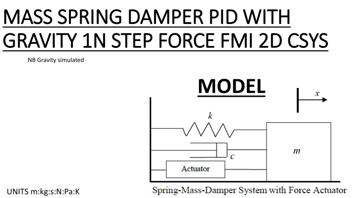
MASS SPRING DAMPER PID WITH MASS SPRING DAMPER PID WITH GRAVITY 1N STEP FORCE FMI 2D CSYS GRAVITY 1N STEP FORCE FMI 2D CSYS NB Gravity simulated MODEL UNITS m:kg:s:N:Pa:K
LS-DYNA 2D MODEL Y=1.5 Y=1.0 Y=0.5 Y=0.0
Mass PID 201 1kg 10 nodes on PID 201 Weight/Node= 1*9.8/10 N (0.98N/Node) Simulating gravity (typical) 10 nodes in total 1N Step Force Spring and Damper fixed to ground Motion in y direction only
Only for FMI Non-Wrapper, LSDYNA is Master, FMU is Slave, no TCP-IP NB. Non Wrapper means NO Third Party Software used in the simulation, all done within LS-DYNA
SCENARIOS INVESTIGATED CASE 0 : NO FMU NO PID CONTROLLER CASE 1 : 1F : Kp = 300.0 Ki= 0.0 Kd=0.0 CASE 2 : 1G : Kp = 300.0 Ki= 0.0 Kd=10.0 CASE 3 : 1H Kp = 30.0 Ki= 70.0 Kd=0.0 CASE 4 : 1H Kp = 350.0 Ki= 300.0 Kd=50.0
CASE 0 : NO FMU NO PID CONTROLLER 1N Step Force Applied Gravity Applied
C:\...\FMI_Manager_v2\fmu_tpl\fmi_udf.c -C++ file- CASE 1 : Kp code CASE 2 : Kp and Kd code CASE 3 : Kp, Kd and Ki code
CASE 1 : 2F : Kp = VARIABLE Ki= 0.0 Kd=0.0 Kp=150 Kp=300 Kp=600
CASE 2 : 2G : Kp = 300.0 Ki= 0.0 Kd=VARIABLE Kd=25 Kd=50 Kd=100
CASE 3 : 2G : Kp = 350.0 Ki= VARIABLE Kd=50.0 Ki=150 Ki=300 Ki=600
LS-DYNA VERSION & RUNTIMES GEN MODEL RUNTIME COSIM MODEL RUNTIME LS-DYNA VERSION
HOW TO RUN 1. Build the BASE model without the FMU information, this is a standard LS-DYNA input keyword deck. 2. Generate the GEN model by adding the *COSIMULATION_FMI_INTERFACE, and *COSIMULATION_FMI_CONTROL files Also change *CONTROL_TIME 3. Generate the COSIM model by adding the *COSIMULATION_FMI_INTERFACE, and *COSIMULATION_FMI_CONTROL files Also change *CONTROL_TIME
4. Run the GEN model (Folder created) (FMU created)
5. Run the COSIM model (d3plot files created)
PARAMETERS USED (PCOEF1) (ICOEF1) (DCOEF1)