Metal Forming Processes and High Energy Rate Forming (HERF) Explained
Learn about metal forming, a process that involves obtaining desired shapes and sizes through plastic deformation, as well as the high energy rate forming (HERF) processes that enhance productivity and efficiency in metalworking. Understand the principles, benefits, and factors to consider when selecting an HERF process for optimal results.

Download Presentation

Please find below an Image/Link to download the presentation.
The content on the website is provided AS IS for your information and personal use only. It may not be sold, licensed, or shared on other websites without obtaining consent from the author. If you encounter any issues during the download, it is possible that the publisher has removed the file from their server.
You are allowed to download the files provided on this website for personal or commercial use, subject to the condition that they are used lawfully. All files are the property of their respective owners.
The content on the website is provided AS IS for your information and personal use only. It may not be sold, licensed, or shared on other websites without obtaining consent from the author.
E N D
Presentation Transcript
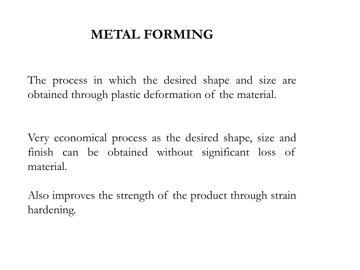
METAL FORMING The process in which the desired shape and size are obtained through plastic deformation of the material. Very economical process as the desired shape, size and finish can be obtained without significant loss of material. Also improves the strength of the product through strain hardening.
High Energy Rate Forming (HERF) Processes Introduction: The forming processes are affected by the strain rate. Effects of strain rates during forming: The flow stress increases with strain rates The temperature of work is increases due to adiabatic heating. Improved lubrication if lubricating film is maintained. Many difficult to form materials like Titanium and Tungsten alloys, can be deformed under high strain rates.
HERF Vs Conventional Forming Conventional Forming
Flanged and deep recessing parts Plane Contoured
Principle / important features of HERF The energy of deformation is delivered at a much higher rate than in conventional practice. Larger energy is applied for a very short interval of time. The velocity of deformation is very large and hence these are also called High Velocity Forming (HVF) processes. Many metals tend to deform more readily under extra fast application of force. Large parts can be easily formed by this technique.
For many metals, the elongation to fracture increases with strain rate beyond the usual metal working range, until a critical strain rate is achieved, where the ductility drops sharply. The strain rate dependence of strength increases with increasing temperature. The yield stress and flow stress at lower plastic strains are more dependent on strain rate than the tensile strength. High rates of strain cause the yield
Factors to be considered while selecting an HERF process: Size of work piece Geometry of deformation Behavior of work material under high strain rates Energy requirements/ source Cost of tooling / die Cycle time Overall capital investment Safety considerations.
Advantages of HERF Processes Production rates are higher, as parts are made at a rapid rate. Die costs are relatively lower. Tolerances can be easily maintained. Versatility of the process it is possible to form most metals including difficult to form metals. No or minimum spring back effect on the material after the process.
Production cost is low as power hammer (or press) is eliminated in the process. Hence it is economically justifiable. Complex shapes / profiles can be made much easily, as compared to conventional forming. The required final shape/ dimensions are obtained in one stroke (or step), thus eliminating intermediate forming steps and pre forming dies. Suitable for a range of production volume such as small numbers, batches or mass production.
Limitations: 1. Highly skilled personnel are required. 2. Not suitable to highly brittle materials 3. Source of energy (chemical explosive or electrical) must be handled carefully. 4. Governmental regulations/ procedures / safety norms must be followed. 5. Dies need to be much bigger to withstand high energy rates and shocks and to prevent cracking. 6. Controlling the application of energy is critical as it may crack the die or work.
Applications: 1. In ship building to form large plates / parts (up to 25 mm thick). 2. Bending thick tubes/ pipes (up to 25 mm thick). 3. Crimping (compress into small folds) of metal strips. 4. Radar dishes. 5. Elliptical domes used in space applications. 6. Cladding of two large plates of dissimilar metals.
Types of HERF Processes: 1. Explosive Forming 2. Electro Hydraulic Forming 3. Magnetic Pulse Forming
(1) Explosive Forming Introduction: A punch in conventional forming is replaced by an explosive charge. Explosives used can be: High energy chemicals like TNT, RDX, and Dynamite. Gaseous mixtures Propellants. Types of explosive forming: 1) Unconfined type or Stand off technique 2) Confined type or Contact technique
1) Unconfined type (or Stand off technique) Principle: The work is firmly supported on the die and the die cavity is evacuated. A explosive is placed suitably in water medium at a definite stand off distance from the work. definite quantity of On detonation of the explosive charge, a pressure pulse (or a shock wave) of very high intensity is produced.
1) Unconfined type (or Stand off technique).. A gas bubble is also produced which expands spherically and then collapses. When the pressure pulse impinges against the work (plate or sheet), the metal is deformed into the die with a high velocity of around 120 m/s (430km/h). The vacuum is necessary in the die to prevent adiabatic heating of the work which may lead to oxidation
1) Unconfined type (or Stand off technique).. Role of water: Acts as energy transfer medium Ensures uniform transmission of energy Muffles the sound of explosion Cushioning/ smooth application of energy on the work without direct contact.
1) Unconfined type (or Stand off technique).. Process Variables Type and amount of explosive: wide range of explosives are available. Stand off distance SOD- (Distance between work piece and explosive): Optimum SOD must be maintained. The medium used to transmit energy: water is most widely used. Work size Work material properties Vacuum in the die
1) Unconfined type (or Stand off technique).. Advantages: Shock wave is efficiently transmitted through water and energy is transmitted effectively on the work Less noise Less probability of damage to work. Large and thick parts can be easily formed Economical, when compared to a hydraulic press
1) Unconfined type (or Stand off technique).. Limitations: Optimum SOD is essential for proper forming operation. Vacuum is essential and hence it adds to the cost. Dies must be larger and thicker to withstand shocks. Not suitable for small and thin works. Explosives must be carefully handled according to the regulations of the government. Applications: Ship building, Radar dish, Elliptical domes in space applications
2) Confined System ( or Contact Technique) Principle: The pressure pulse or shock wave produced is in direct contact with the work piece (usually tubular) and hence the energy is directly applied on the work without any water medium. The tube collapses into the die cavity and is formed. It is used for bulging and flaring operations.
Advantages: Entire shock wave front is utilized as there is no loss in water. More efficient as compared to unconfined type. Disadvantages: More hazard of die failure Vacuum is required in the die Air present in the work piece (tube) is compressed leading to heating. Not suitable for large and thick plates. Applications: Bulging and flaring (gradually become wider at one end) of tubes.
Electro Hydraulic Forming Principle A sudden electrical discharge in the form of sparks is produced between electrodes and this discharge produces a shock wave in the water medium. This shock wave deforms the work plate and collapses it into the die.
Electro hydraulic Forming . The characteristics of this process are similar to those of explosive forming. The major difference, however, is that a chemical explosive is replaced by a capacitor bank, which stores the electrical energy. The capacitor is charged through a charging circuit. When the switch is closed, a spark is produced between electrodes and a shock wave or pressure pulse is created. The energy released is much lesser than that released in explosive forming.
Electro hydraulic Forming . Process Characteristics: Stand off distance: It must be optimum. Capacitor used: The energy of the pressure pulse depends on the size of capacitor. Transfer medium: Usually water is used. Vacuum: the die cavity must be evacuated to prevent adiabatic heating of the work due to a sudden compression of air. Material properties with regard to the application of high rates of strain.
Electro hydraulic Forming . Advantages: 1. Better control of the pressure pulse as source of energy is electrical- which can be easily controlled. 2. Safer in handling than the explosive materials. 3. More suitable if the work size is small to medium. 4. Thin plates can be formed with smaller amounts of energy. 5. The process does not depend on the electrical properties of the work material.
Electro hydraulic Forming . Limitations: 1. Suitable only for smaller works 2. Need for vacuum makes the equipment more complicated. 3. Proper SOD is necessary for effective process. Applications: They include smaller radar dish, cone and other shapes in thinner and small works.
Electromagnetic forming The electrical energy stored in a capacitor bank is used to produce opposing magnetic fields around a tubular work piece, surrounded by current carrying coils. The coil is firmly held and hence the work piece collapses into the die cavity due to magnetic repelling force, thus assuming die shape.
Electromagnetic forming .. (a) Schematic illustration of the magnetic-pulse forming process used to form a tube over a plug. (b) Aluminum tube collapsed over a hexagonal plug by the magnetic-pulse forming process.
Electromagnetic forming . Fig. Electro Magnetic Forming
Electromagnetic forming . Process details/ Steps: The electrical energy is stored in the capacitor bank. The tubular work piece is mounted on a mandrel having the die cavity to produce shape on the tube. A primary coil is placed around the tube and mandrel assembly. When the switch is closed, the energy is discharged through the coil
Electromagnetic forming . Process details/ Steps .. The coil produces a varying magnetic field around it. In the tube a secondary current is induced, which creates its own magnetic field in the opposite direction. The directions of these two magnetic fields oppose one another and hence the rigidly held coil repels the work into the die cavity. The work tube collapses into the die, assuming its shape.
Electromagnetic forming . Process parameters: Work piece size Electrical conductivity of the work material. Size of the capacitor bank The strength of the current, which decides the strength of the magnetic field and the force applied. Insulation on the coil. Rigidity of the coil.
Electromagnetic forming . Advantages: I. Suitable for small tubes II. Operations like collapsing, bending and crimping can be easily done. III. Electrical energy applied can be precisely controlled and hence the process is accurately controlled. IV. The process is safer compared to explosive forming. V. Wide range of applications.
Electromagnetic forming . Limitations: i. Applicable only for electrically conducting materials. ii. Not suitable for large work pieces. iii. Rigid clamping of primary coil is critical. iv. Shorter life of the coil due to large forces acting on it. Applications: i. Crimping of coils, tubes, wires ii. Bending of tubes into complex shapes iii. Bulging of thin tubes.
Rubber pad forming Rubber pad forming (RPF) is a metal working process where sheet metal is pressed between a die and a rubber block, made of polyurethane. Under pressure, the rubber and sheet metal are driven into the die and conform to its shape, forming the part. The rubber pads can have a general purpose shape, like a membrane. Alternatively, they can be machined in the shape of die or punch. Due to the material properties of the rubber, the pad will regain its original shape when retracted from the tool.
Rubber pad forming. Rubber pad forming can be accomplished in many different ways. In general, an elastic upper die, usually made of rubber, is connected to a hydraulic press. A rigid lower die, often called a form block, provides the mold for the sheeted metal to be formed. The rubber exerts nearly equal pressure on all work piece surfaces due to its incompressibility. The multidirectional nature of the force from the rubber pad produces variable radius during forming and thus enhances uniform elongation of the work piece.
Rubber pad forming. Polyurethanes are used widely because of their resistance to abrasion, long fatigue life and resistance to damage by burrs or sharp edges of the sheet blank. Types of Rubber pad forming processes Guerin process Marform deep drawing process Verson Hydroform process Masleennikov s process
Guerin process Oldest and simplest rubber pad forming process. As the ram descends, the rubber presses the blank around the form block, thus forming the work piece. The rubber-pad retainer fits closely around the platen, forming an enclosure that traps the rubber as pressure is applied. Aluminum alloys, Austenitic Stainless Steels and titanium alloys can be shallow drawn using this process. The pressure produced in the Guerin process is ordinarily between 6.9 and 48 Mpa.
Guerin process Advantages Low tooling cost Form block can be made of wood, plastic, or other materials that are easy to shape Rubber pad can be used with different form blocks Process attractive in small quantity production Due to low hardness of the rubber pad, the worked metal is not worn as quickly as in more conventional processes such as deep drawing.
Guerin process LIMITATIONS The wear of the rubber is an issue in larger quantity manufacturing. Lower forming pressure and consequently large amount of wrinkles. Low production rate Since the amount of pressure exerted by rubber is limited by the strength of rubber itself, forming of sheet metal parts with small forming radius may not be possible. Limited to forming moderately shallow, recessed parts, having simple flanges and having simple configuration due to lower strength of rubber.
Guerin process APPLICATIONS Rubber pad forming has been used in production lines for many years. Up to 60% of all sheet metal parts in the aerospace industry are fabricated using this process. The most relevant applications are aerospace, automotive and defense fields. It is frequently used in prototyping and production of small quantities of sheet metal parts.

 Processes")
 Process")


 is")


 Explosive Forming")
 Unconfined type (or Stand off technique)")
 Unconfined type (or Stand off technique)…..")
 Unconfined type (or Stand off technique)…..")
 Unconfined type (or Stand off technique)…..")
 Unconfined type (or Stand off technique)…..")
 Unconfined type (or Stand off technique)…..")
 Unconfined type (or Stand off technique)…..")
 Confined System ( or Contact Technique)")
 Confined System ( or Contact Technique) …..")