Mounting of Heavy Components in Target Spectrometer Support
This detailed post discusses the interfaces required for mounting heavy components in a target spectrometer support, including specifications for various components, proposal for creating interface documents, and methods for mounting heavy components using concrete blocks in the spectrometer setup. Evgeny Koshurnikov's proposals and presentations are highlighted, providing valuable insights for the project.

Uploaded on | 0 Views
Download Presentation

Please find below an Image/Link to download the presentation.
The content on the website is provided AS IS for your information and personal use only. It may not be sold, licensed, or shared on other websites without obtaining consent from the author. If you encounter any issues during the download, it is possible that the publisher has removed the file from their server.
You are allowed to download the files provided on this website for personal or commercial use, subject to the condition that they are used lawfully. All files are the property of their respective owners.
The content on the website is provided AS IS for your information and personal use only. It may not be sold, licensed, or shared on other websites without obtaining consent from the author.
E N D
Presentation Transcript
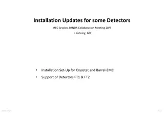
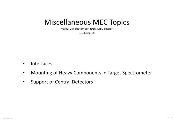
Miscellaneous MEC Topics Mainz, CM September 2016, MEC Session J. L hning, GSI Interfaces Mounting of Heavy Components in Target Spectrometer Support of Central Detectors 1 / 10 2016-09-12
Interfaces Interfaces need to be defined between neighboring components. In 2014, Evgeny Koshurnikov had posted a first draft, which Lars Schmitt had adopted and modified in the EDMS document Detailed Specification for the PANDA Superconducting Solenoid Magnet , s. https://edms.cern.ch/document/1713314/2 From chapter 3.3 of that document: 1. Floor space and geometrical constraints 2. Overall dimensions 3. Rail tracks 4. Detector support 5. Services and cables (recesses in barrel yoke) 6. Muon filter 7. Muon detectors (barrel layers) 8. Backward Endcap EMC 9. Barrel DIRC readout 10. Target system 11. Auxiliary Platform 12. Electronic racks 2 / 10 2016-09-12
Interfaces In his latest CM presentation Evgeny Koshurnikov had named additional interfaces, mainly for the cold mass and the cryostat (s. https://indico.gsi.de/conferenceDisplay.py?confId=4839): 1. Control Dewar with helium supply lines 2. Bus bars of the power supply and control Dewar current leads 3. Control Dewar and target equipment on the top platform 4. Bus bars and helium tubing of the cold mass inside the interface box 5. Ties of the cold mass suspension system and the brackets on the outer surface of the SC coil support cylinder 6. Positions of scaffold stairs to get to the top platform 3 / 10 2016-09-12
Interfaces How should we proceed? Proposal: Generation of one EDMS document for each interface, which has to be checked by the involved system managers and released by the TC. (EDMS type: Engineering - Functional Specifications (EF), release procedure: FAIR-PE) After finishing all interface documents, they should be merged into one big document (proposal by Evgeny Koshurnikov). 4 / 10 2016-09-12
Mounting of Heavy Components in Target Spectrometer concrete block upstream, upper surface 2.1 meter below beam height concrete block downstream Target Spectrometer in maintenance position, concrete blocks may be used for installation of cryostat, barrel-EMC, and FE-EMC. Horizontal dimensions of concrete blocks: only as big as necessary, with horizontal acceleration of heavy parts 1.5 m/s (0.075 g safety factor 2). 5 / 10 2016-09-12
Mounting of Heavy Components in Target Spectrometer cryostat position before move-in beam HEB-700 (length 9.4m, Ix=256dm4), usable for both cryostat and b-EMC support usable for both cryostat and barrel-EMC Target Spectrometer (eastern half hidden), support set-up for cryostat 6 / 10 2016-09-12
Mounting of Heavy Components in Target Spectrometer barrel-EMC in assembly position Max. beam deflection during movement 6 mm gangway around barrel-EMC ranging from -6.8m < z < -1.9m Max. load on downstream support reached when b-EMC in target position: 130 kN Barrel-EMC set-up in assembly position, yellow parts taken from a design that Valeriy Ferapontov had proposed 7 / 10 2016-09-12
Mounting of Heavy Components in Target Spectrometer maintenance position for Central Trackers and BE-EMC auxiliary platform FE-EMC position before move-in rail support for FE-EMC FE-EMC mounting set-up 8 / 10 2016-09-12
Support of Central Detectors barrel-EMC flanges load by STT, MVD, supplies applied only to upper CT-beam ( mass ~100 kg) upper CT-beam downstream support cone (CFRP 1 mm) DIRC barrel (mass of one half ~200 kg) lower CT-beam Model for FEM analysis (western half). CT-beams are supposed to be made of aluminium, main moment of inertia ~280 cm4 9 / 10 2016-09-12
Support of Central Detectors max. deflection of upper CT-beam 0.45 mm (- y) Deflection of CT-beams under all weights (magnification factor 400). Colours indicate the vertical displacement. Downstream support cone is able to carry considerable radial loads but hardly any axial load. 10 / 10 2016-09-12