New Holland CR8080 Tier 4a Combine Service Repair Manual Instant Download 2
New Holland CR8080 Tier 4a Combine Service Repair Manual Instant Download 2

Download Presentation

Please find below an Image/Link to download the presentation.
The content on the website is provided AS IS for your information and personal use only. It may not be sold, licensed, or shared on other websites without obtaining consent from the author. If you encounter any issues during the download, it is possible that the publisher has removed the file from their server.
You are allowed to download the files provided on this website for personal or commercial use, subject to the condition that they are used lawfully. All files are the property of their respective owners.
The content on the website is provided AS IS for your information and personal use only. It may not be sold, licensed, or shared on other websites without obtaining consent from the author.
E N D
Presentation Transcript
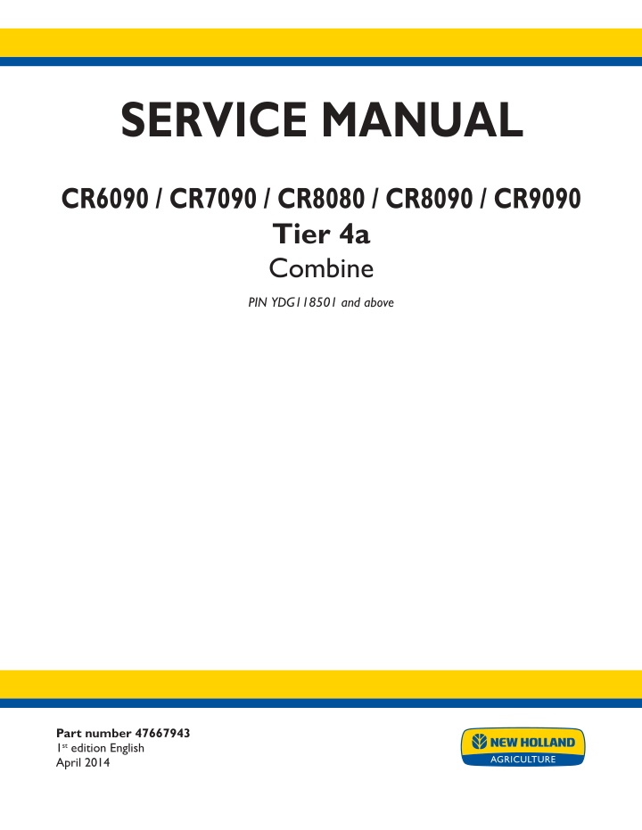
SERVICE MANUAL CR6090 / CR7090 / CR8080 / CR8090 / CR9090 Tier 4a Combine PIN YDG118501 and above Part number 47667943 1st edition English April 2014 Printed in U.S.A. Copyright 2014 CNH Industrial America LLC. All Rights Reserved. New Holland is a registered trademark of CNH Industrial America LLC. Racine Wisconsin 53404 U.S.A.
Link Product / Engine Product Market Product North America North America North America North America North America Engine CR6090 [YDG118501 - ] CR7090 [YDG118501 - ] CR8080 [YDG118501 - ] CR8090 [YDG118501 - ] CR9090 [YDG118501 - ] F2CFE613A*A F2CFE613A*A F3AFE613A*A F3AFE613A*A F3BFE613D*A 47667943 24/04/2014
Contents INTRODUCTION Engine....................................................................................... 10 [10.001] Engine and crankcase ............................................................. 10.1 [10.202] Air cleaners and lines .............................................................. 10.2 [10.304] Engine lubrication system.......................................................... 10.3 [10.310] Aftercooler.......................................................................... 10.4 [10.400] Engine cooling system ............................................................. 10.5 [10.414] Fan and drive ...................................................................... 10.6 [10.418] Rotary screen ...................................................................... 10.7 [10.450] Engine air compressor ............................................................. 10.8 [10.500] Selective Catalytic Reduction (SCR) exhaust treatment........................... 10.9 Main gearbox and drive............................................................... 14 [14.100] Main gearbox and drive ............................................................ 14.1 Transmission.............................................................................. 21 [21.114] Mechanical transmission ........................................................... 21.1 [21.130] Mechanical transmission external controls......................................... 21.2 [21.145] Gearbox internal components...................................................... 21.3 [21.182] Differential.......................................................................... 21.4 Front axle system ....................................................................... 25 [25.108] Final drive hub, steering knuckles, and shafts ..................................... 25.1 [25.100] Powered front axle ................................................................. 25.2 [25.310] Final drives......................................................................... 25.3 Rear axle system........................................................................ 27 [27.100] Powered rear axle.................................................................. 27.1 Hydrostatic drive......................................................................... 29 [29.100] Transmission and steering hydrostatic control..................................... 29.1 47667943 24/04/2014
https://www.ebooklibonline.com Hello dear friend! Thank you very much for reading. Enter the link into your browser. The full manual is available for immediate download. https://www.ebooklibonline.com
[29.134] Two-speed assembly............................................................... 29.2 [29.202] Hydrostatic transmission ........................................................... 29.3 [29.204] Reservoir, cooler, and lines ........................................................ 29.4 [29.218] Pump and motor components...................................................... 29.5 [29.300] Rear hydrostatic transmission...................................................... 29.6 Brakes and controls .................................................................... 33 [33.110] Parking brake or parking lock ...................................................... 33.1 [33.202] Hydraulic service brakes ........................................................... 33.2 Hydraulic systems....................................................................... 35 [35.000] Hydraulic systems.................................................................. 35.1 [35.102] Pump control valves................................................................ 35.2 [35.106] Variable displacement pump ....................................................... 35.3 [35.220] Auxiliary hydraulic pump and lines................................................. 35.4 [35.300] Reservoir, cooler, and filters........................................................ 35.5 [35.359] Main control valve.................................................................. 35.6 [35.410] Header or attachment height system .............................................. 35.7 [35.415] Header or attachment tilting system ............................................... 35.8 [35.440] Grain tank unload system.......................................................... 35.9 [35.450] Traction variator system.......................................................... 35.10 [35.518] Reel control system .............................................................. 35.11 [35.536] Crop processor system .......................................................... 35.12 [35.602] Header or attachment leveling system........................................... 35.13 [35.760] Header reverser drive............................................................ 35.14 [35.796] Chaff spreader control ........................................................... 35.15 Steering..................................................................................... 41 [41.101] Steering control .................................................................... 41.1 [41.200] Hydraulic control components...................................................... 41.2 [41.206] Pump............................................................................... 41.3 47667943 24/04/2014
[41.216] Cylinders ........................................................................... 41.4 [41.432] Autoguidance steering ............................................................. 41.5 Tracks and track suspension........................................................ 48 [48.100] Tracks .............................................................................. 48.1 [48.130] Track frame and driving wheels.................................................... 48.2 [48.134] Track tension units ................................................................. 48.3 Cab climate control..................................................................... 50 [50.100] Heating............................................................................. 50.1 [50.104] Ventilation .......................................................................... 50.2 [50.200] Air conditioning..................................................................... 50.3 Electrical systems....................................................................... 55 [55.000] Electrical system ................................................................... 55.1 [55.010] Fuel injection system............................................................... 55.2 [55.011] Fuel tank system ................................................................... 55.3 [55.012] Engine cooling system ............................................................. 55.4 [55.013] Engine oil system .................................................................. 55.5 [55.014] Engine intake and exhaust system................................................. 55.6 [55.015] Engine control system.............................................................. 55.7 [55.019] Hydrostatic drive control system ................................................... 55.8 [55.024] Transmission control system....................................................... 55.9 [55.029] Gearbox electric system ......................................................... 55.10 [55.030] Service brake electrical system .................................................. 55.11 [55.031] Parking brake electrical system.................................................. 55.12 [55.036] Hydraulic system control ......................................................... 55.13 [55.050] Heating, Ventilation, and Air-Conditioning (HVAC) control system............... 55.14 [55.051] Cab Heating, Ventilation, and Air-Conditioning (HVAC) controls................. 55.15 [55.100] Harnesses and connectors....................................................... 55.16 [55.201] Engine starting system........................................................... 55.17 47667943 24/04/2014
[55.202] Cold start aid ..................................................................... 55.18 [55.301] Alternator......................................................................... 55.19 [55.302] Battery............................................................................ 55.20 [55.404] External lighting .................................................................. 55.21 [55.408] Warning indicators, alarms, and instruments .................................... 55.22 [55.421] Feeding control system .......................................................... 55.23 [55.423] Cleaning control system.......................................................... 55.24 [55.426] Harvest material flow control system............................................. 55.25 [55.512] Cab controls...................................................................... 55.26 [55.518] Wiper and washer system........................................................ 55.27 [55.519] Cab brake controls ............................................................... 55.28 [55.520] Cab harvesting controls.......................................................... 55.29 [55.610] Ground speed control ............................................................ 55.30 [55.618] Reverser electric control ......................................................... 55.31 [55.624] Residue handling control......................................................... 55.32 [55.628] Threshing electrical control ...................................................... 55.33 [55.640] Electronic modules............................................................... 55.34 [55.661] Cab header controls.............................................................. 55.35 [55.662] Header height control ............................................................ 55.36 [55.670] Header leveling control........................................................... 55.37 [55.780] Shaker shoe leveling system control............................................. 55.38 [55.785] Precision farming system ........................................................ 55.39 [55.834] Sieve electric control ............................................................. 55.40 [55.836] Rotary separator control ......................................................... 55.41 [55.633] Baler feeding control ............................................................. 55.42 [55.911] Global Positioning System (GPS) ................................................ 55.43 [55.988] Selective Catalytic Reduction (SCR) electrical system .......................... 55.44 [55.DTC] FAULT CODES.................................................................. 55.45 47667943 24/04/2014
Product feeding.......................................................................... 60 [60.105] Floating roll, feed chain, and drive ................................................. 60.1 [60.110] Feeder housing..................................................................... 60.2 [60.112] Stone trapping system ............................................................. 60.3 [60.130] Feeder housing shafts ............................................................. 60.4 [60.150] Feeder drive system ............................................................... 60.5 Threshing .................................................................................. 66 [66.000] Threshing .......................................................................... 66.1 [66.101] Concave conveyor plate ........................................................... 66.2 [66.105] Concave............................................................................ 66.3 [66.110] Concave control system............................................................ 66.4 [66.260] Threshing mechanism drive system ............................................... 66.5 [66.321] Drum/Rotor variator with electrical control ......................................... 66.6 [66.331] Rotor ............................................................................... 66.7 [66.360] Drum/Rotor housing................................................................ 66.8 Residue handling........................................................................ 73 [73.210] Straw chopper drive system........................................................ 73.1 [73.220] Straw chopper frame............................................................... 73.2 [73.230] Straw chopper...................................................................... 73.3 [73.300] Positive Straw Discharge (PSD) ................................................... 73.4 [73.335] Chaff spreader ..................................................................... 73.5 [73.410] Opti-Spread system.............................................................. 73.6 Cleaning.................................................................................... 74 [74.000] Cleaning............................................................................ 74.1 [74.100] Self-leveling frame ................................................................. 74.2 [74.101] Cleaning drive systems ............................................................ 74.3 [74.110] Grain pan........................................................................... 74.4 [74.114] Upper shaker shoe ................................................................. 74.5 47667943 24/04/2014
[74.118] Lower shaker shoe ................................................................. 74.6 [74.130] Fan housing........................................................................ 74.7 [74.136] Fan drive system................................................................... 74.8 [74.140] Tailings return system.............................................................. 74.9 Crop storage / Unloading............................................................. 80 [80.101] Clean grain elevator................................................................ 80.1 [80.150] Grain tank .......................................................................... 80.2 [80.175] Grain tank unload drive system .................................................... 80.3 [80.180] Grain tank unload .................................................................. 80.4 Platform, cab, bodywork, and decals............................................. 90 [90.105] Machine shields and guards ....................................................... 90.1 [90.118] Protections and footboards......................................................... 90.2 [90.124] Pneumatically-adjusted operator seat.............................................. 90.3 [90.150] Cab................................................................................. 90.4 [90.151] Cab interior......................................................................... 90.5 [90.154] Cab doors and hatches ............................................................ 90.6 47667943 24/04/2014
INTRODUCTION 47667943 24/04/2014 1
INTRODUCTION Foreword Soil, air, and water are vital factors of agriculture and life in general. When legislation does not yet rule the treatment of some of the substances required by advanced technology, sound judgment should govern the use and disposal of products of a chemical and petrochemical nature. NOTE: The following are recommendations that may be of assistance: Become acquainted with and ensure that you understand the relative legislation applicable to your country. Where no legislation exists, obtain information from suppliers of oils, filters, batteries, fuels, antifreeze, cleaning agents, etc., with regard to their effect on man and nature and how to safely store, use, and dispose of these substances. Agricultural consultants will, in many cases, be able to help you as well. Helpful hints Avoid filling tanks using cans or inappropriate pressurized fuel delivery systems that may cause considerable spillage. In general, avoid skin contact with all fuels, oils, acids, solvents, etc. Most of them contain substances that may be harmful to your health. Modern oils contain additives. Do not burn contaminated fuels and or waste oils in ordinary heating systems. Avoid spillage when draining off used engine coolant mixtures, engine, gearbox and hydraulic oils, brake fluids, etc. Do not mix drained brake fluids or fuels with lubricants. Store them safely until they can be disposed of in a proper way to comply with local legislation and available resources. Modern coolant mixtures, i.e. antifreeze and other additives, should be replaced every two years. They should not be allowed to get into the soil, but should be collected and disposed of properly. Do not open the air-conditioning system yourself. It contains gases that should not be released into the atmosphere. Your NEW HOLLAND dealer or air conditioning specialist has a special extractor for this purpose and will have to recharge the system properly. Repair any leaks or defects in the engine cooling or hydraulic system immediately. Do not increase the pressure in a pressurized circuit as this may lead to a component failure. Protect hoses during welding as penetrating weld splatter may burn a hole or weaken them, allowing the loss of oils, coolant, etc. 47667943 24/04/2014 5
INTRODUCTION Safety rules Personal safety This is the safety alert symbol. It is used to alert you to potential personal injury hazards. Obey all safety messages that follow this symbol to avoid possible death or injury. Throughout this manual you will find the signal words DANGER, WARNING, and CAUTION followed by special in- structions. These precautions are intended for the personal safety of you and those working with you. Read and understand all the safety messages in this manual before you operate or service the machine. DANGER indicates a hazardous situation which, if not avoided, will result in death or serious injury. WARNING indicates a hazardous situation which, if not avoided, could result in death or serious injury. CAUTION, used with the safety alert symbol, indicates a hazardous situation which, if not avoided, could result in minor or moderate injury. FAILURE TO FOLLOW DANGER, WARNING, AND CAUTION MESSAGES COULD RESULT IN DEATH OR SERIOUS INJURY. Machine safety NOTICE: Notice indicates a situation which, if not avoided, could result in machine or property damage. Throughout this manual you will find the signal word Notice followed by special instructions to prevent machine or property damage. The word Notice is used to address practices not related to personal safety. Information NOTE: Note indicates additional information which clarifies steps, procedures, or other information in this manual. Throughout this manual you will find the word Note followed by additional information about a step, procedure, or other information in the manual. The word Note is not intended to address personal safety or property damage. 47667943 24/04/2014 6
INTRODUCTION Safety rules - Personal safety Carefully study these precautions, and those included in the external attachment operators manual, and insist that they be followed by those working with and for you. 1. Thoroughly read and understand this manual and the attachment Operator s Manual before operating this or any other equipment. 2. Be sure all people and pets are clear of the machine before starting. Sound the horn, if equipped, three times before starting engine. 3. Only the operator should be on the machine when in operation. Never allow anyone to climb on to the machine while it is in motion. If the machine is equipped with an Instructors Seat, this must only be used for training purposes. Passengers must not be allowed to use the Instructors Seat. 4. Keep all shields in place. Never work around the machine or any of the attachments while wearing loose clothing that might catch on moving parts. 5. Observe the following precautions whenever lubricating the machine or making adjustments. Disengage all clutching levers or switches. Lower the attachment, if equipped, to the ground or raise the attachment completely and engage the cylinder safety locks. Completing these actions will prevent the attachment from lowering unexpectedly. Engage the parking brake. Shut off the engine and remove the key. Wait for all machine movement to stop before leaving the operators platform. 6. Always keep the machine in gear while travelling downhill. 7. The machine should always be equipped with sufficient front or rear axle weight for safe operation. 8. Under some field conditions, more weight may be required at the front or rear axle for adequate stability. This is especially important when operating in hilly conditions or/when using heavy attachments. 9. Always lower the attachment, shut off the engine, set the parking brake, engage the transmission gears, remove the key and wait for all machine movement to stop before leaving the operators platform. 10. If the attachment or machine should become obstructed or plugged; set the parking brake, shut off the engine and remove the key, engage the transmission gears, wait for all machine or attachment motion to come to a stop, before leaving the operators platform to removing the obstruction or plug. 11. Never disconnect or make any adjustments to the hydraulic system unless the machine and/or the attachment is lowered to the ground or the safety lock(s) is in the engaged position. 12. Use of the flashing lights is highly recommended when operating on a public road. 13. When transporting on a road or highway, use accessory lights and devices for adequate warning to the opera- tors of other vehicles. In this regard, check local government regulations. Various safety lights and devices are available from your NEW HOLLAND dealer. 14. Practice safety 365 days a year. 15. Keep all your equipment in safe operating condition. 16. Keep all guards and safety devices in place. 17. Always set the parking brake, shut off the engine and remove the key, engage the transmission gears, wait for all machine or attachment motion to come to a stop, before leaving the operators platform to service the machine and attachment. 18. Remember: A careful operator is the best insurance against an accident. 19. Extreme care should be taken in keeping hands and clothing away from moving parts. 47667943 24/04/2014 7
SERVICE MANUAL Engine CR6090 [YDG118501 - ] CR7090 [YDG118501 - ] CR8080 [YDG118501 - ] CR8090 [YDG118501 - ] CR9090 [YDG118501 - ] 47667943 24/04/2014 10
Engine - Engine and crankcase Engine - Remove NA CR Series Tier IV WARNING Avoid injury! Always do the following before lubricating, maintaining, or servicing the machine. 1. Disengage all drives. 2. Engage parking brake. 3. Lower all attachments to the ground, or raise and engage all safety locks. 4. Shut off engine. 5. Remove key from key switch. 6. Switch off battery key, if installed. 7. Wait for all machine movement to stop. Failure to comply could result in death or serious injury. W0047A DANGER Unexpected movement! Make sure parking brake is applied. Secure machine with wheel chocks. Failure to comply will result in death or serious injury. D0013A Prior operation: Battery - Disconnect key switch (55.302) Prior operation: Engine cooling system - Drain fluid (10.400) Prior operation: Engine lubrication system - Drain fluid (10.304) Prior operation: Engine hood - Remove and Engine Shielding Removal (90.105) Prior operation: Air cleaner - Remove (10.202) Prior operation: Aftercooler - Remove charge air cooler tubes (CAC) (10.310) Prior operation: Deaeration tank - Remove (10.400) Prior operation: Engine cooling system - Remove Coolant Hoses (10.400) Prior operation: Fan and drive - Remove (10.414) Prior operation: Selective Catalytic Reduction (SCR) exhaust treatment - Remove return line (10.500) Prior operation: Diesel Exhaust Fluid (DEF)/AdBlue lines - Remove DEF heater hoses (10.500) Prior operation: Diesel Exhaust Fluid (DEF)/AdBlue delivery line to dosing injector - Remove (10.500) Prior operation: Selective Catalytic Reduction (SCR) muffler and catalyst - Remove (10.500) Prior operation: Air conditioning - Service instruction (50.200) 47667943 24/04/2014 10.1 [10.001] / 4
Engine - Engine and crankcase 1. Remove the elastic belt from the a/c compressor. NOTE: Belt can be cut from the a/c compressor, since it must be replaced with a new one after each disassembly operation. 2. Disconnect the electrical connectors (1) and remove the four mounting bolts (2) from the air conditioning compressor (3). Remove the compressor from the en- gine and tie the assembly out of the way. NOTE: It may be necessary to cut the wire ties to the elec- trical wiring harness to pull back and tie the a/c unit out of the way. 1 83070255 3. Close valve (1) at fuel tank. 4. Disconnect the electrical connector (2) to the fuel pump (6). NOTE: Use a clean container, with adequate capacity to catch any fuel from the fuel line. 2 86063503 5. Loosen the fitting (1) and disconnect the fuel line (2) from the fuel pump. Cap the end of the fuel line and tie it out of the way. 3 86070256 6. Loosen the fitting (1) and disconnect the return to tank fuel line (2) from the tee-connector (3). Cap the end of the fuel line and tie it out of the way. 4 86070257 47667943 24/04/2014 10.1 [10.001] / 5
Engine - Engine and crankcase 7. Disconnect the main engine electrical harness connec- tor (1). 5 86063847 8. Open the rotary screen door and disconnect the rotary screen brush electrical connector (1) if installed. 6 10013132 9. Feed the connector and wire loom (1) and grommet (2) through the hole in the radiator frame. Secure the wire loom and connector, if installed, to the engine to prevent damage during removal. NOTE: Removal of the rubber grommet in the radiator frame hole may be necessary to remove the radiator screen brush electrical connector. 7 10013133_794 10. Cut the wire ties (1) and separate the engine wire har- ness (2) from the gearbox wire harness (3). Secure each harness to prevent damage during engine re- moval. 8 10013126 47667943 24/04/2014 10.1 [10.001] / 6
Suggest: If the above button click is invalid. Please download this document first, and then click the above link to download the complete manual. Thank you so much for reading
Engine - Engine and crankcase 11. Loosen and remove the nut (1). Disconnect the main starter cable (2) from the starter solenoid (3). 9 86070258 12. Attach a suitable chain to the front lift eye (1) at the front of the engine. 10 86070259 13. Attach a suitable chain to the back lift eye (1) at the rear of the engine. 11 86070260 14. Connect the lift chain to a suitable lifting device. 15. Raise the lifting device enough to support the engine during removal of the engine mounting bolts. NOTE: Illustration is for reference only. It may not be the actual engine. NOTE: The lifting device should be rated for at least 907.2 kg (2000 lb). Allow enough clearance to lift the engine from the combine, approximately 7.0 m (23 ft) from the floor. 12 10013136 47667943 24/04/2014 10.1 [10.001] / 7
https://www.ebooklibonline.com Hello dear friend! Thank you very much for reading. Enter the link into your browser. The full manual is available for immediate download. https://www.ebooklibonline.com