New Holland CX5090 Tier 3 Combine Harvester Service Repair Manual Instant Download
New Holland CX5090 Tier 3 Combine Harvester Service Repair Manual Instant Download

Download Presentation

Please find below an Image/Link to download the presentation.
The content on the website is provided AS IS for your information and personal use only. It may not be sold, licensed, or shared on other websites without obtaining consent from the author. If you encounter any issues during the download, it is possible that the publisher has removed the file from their server.
You are allowed to download the files provided on this website for personal or commercial use, subject to the condition that they are used lawfully. All files are the property of their respective owners.
The content on the website is provided AS IS for your information and personal use only. It may not be sold, licensed, or shared on other websites without obtaining consent from the author.
E N D
Presentation Transcript
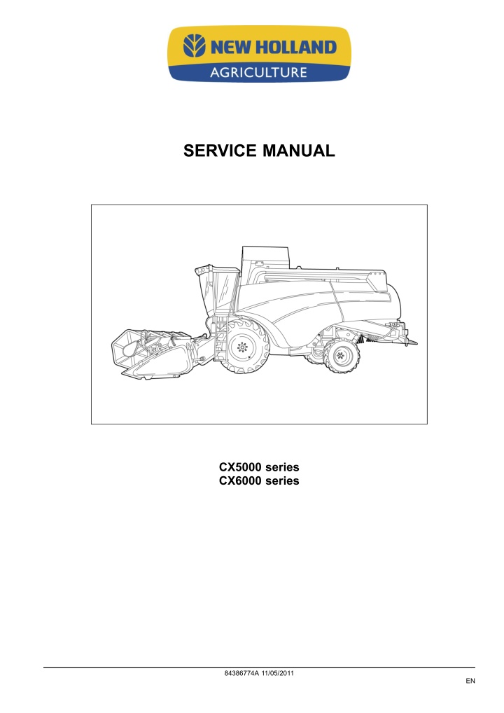
SERVICE MANUAL CX5000 series CX6000 series 84386774A 11/05/2011 EN
Contents INTRODUCTION HYDRAULIC, PNEUMATIC, ELECTRICAL, ELECTRONIC SYSTEMS A PRIMARY HYDRAULIC POWER SYSTEM.............................................. A.10.A PNEUMATIC SYSTEM ................................................................... A.20.A ELECTRICAL POWER SYSTEM ........................................................ A.30.A ELECTRONIC SYSTEM ................................................................. A.50.A FAULT CODES ........................................................................... A.50.A ENGINE AND PTO IN................................................................... B EXHAUST SYSTEM Emissions control .................................................. B.40.B TRANSMISSION, DRIVE AND PTO OUT........................................ C TRANSMISSION Mechanical ............................................................ C.20.B TRANSMISSION Hydrostatic............................................................. C.20.F PROCESS DRIVE Primary process drive................................................ C.50.B AXLES, BRAKES AND STEERING................................................. D FRONT AXLE ............................................................................ D.10.A REAR AXLE .............................................................................. D.12.A 2WD-4WD SYSTEM Hydrostatic......................................................... D.14.E STEERING Hydraulic..................................................................... D.20.C STEERING Mechanical .................................................................. D.20.B SERVICE BRAKE Hydraulic.............................................................. D.30.C PARKING BRAKE Mechanical ........................................................... D.32.B FRAME AND CAB ........................................................................ E USER PLATFORM ....................................................................... E.34.A ENVIRONMENT CONTROL Heating system ............................................ E.40.B ENVIRONMENT CONTROL Air-conditioning system.................................... E.40.C FRAME POSITIONING ................................................................. F FRAME LEVELLING ..................................................................... F.30.A TOOL POSITIONING.................................................................... G 84386774A 11/05/2011
LIFTING .................................................................................. G.10.A LEVELLING .............................................................................. G.30.A CROP PROCESSING................................................................... K FEEDING Reel feeding................................................................... K.25.B FEEDING Header feeding................................................................ K.25.D FEEDING Feeder housing ............................................................... K.25.E THRESHING Conventional threshing .................................................... K.40.B SEPARATING Beating.................................................................... K.42.B SEPARATING Rotary separator.......................................................... K.42.C SEPARATING Straw flow beater ......................................................... K.42.F SEPARATING Straw walker.............................................................. K.42.E CLEANING Primary cleaning............................................................. K.62.B CLEANING Tailings return system ....................................................... K.62.C STORING AND HANDLING Grain storing ............................................... K.60.B UNLOADING Grain unloading............................................................ K.72.B 84386774A 11/05/2011
https://www.ebooklibonline.com Hello dear friend! Thank you very much for reading. Enter the link into your browser. The full manual is available for immediate download. https://www.ebooklibonline.com
INTRODUCTION 84386774A 11/05/2011 1
INTRODUCTION Foreword IMPORTANT INFORMATION All repair and maintenance works listed in this manual must be carried out only by staff belonging to the NEW HOL- LAND Service network, strictly complying with the instructions given and using, whenever required, the special tools. Anyone who carries out the above operations without complying with the prescriptions shall be responsible for the subsequent damages. The manufacturer and all the organizations of its distribution chain, including - without limitation - national, regional or local dealers, reject any responsibility for damages due to the anomalous behavior of parts and/or components not approved by the manufacturer himself, including those used for the servicing or repair of the product manufactured or marketed by the Manufacturer. In any case, no warranty is given or attributed on the product manufactured or marketed by the Manufacturer in case of damages due to an anomalous behavior of parts and/or components not approved by the Manufacturer. No reproduction, though partial of text and illustrations allowed 84386774A 11/05/2011 3
INTRODUCTION Foreword Technical Information This manual has been produced by a new technical information system. This new system is designed to deliver technical information electronically through CD-ROM and in paper manuals. A coding system called ICE has been developed to link the technical information to other Product Support functions e.g. Warranty. Technical information is written to support the maintenance and service of the functions or systems on a customers machine. When a customer has a concern on his machine it is usually because a function or system on his machine is not working at all, is not working efficiently, or is not responding correctly to his commands. When you refer to the technical information in this manual to resolve that customers concern, you will find all the information classified using the new ICE coding, according to the functions or systems on that machine. Once you have located the technical information for that function or system then you will find all the mechanical, electrical or hydraulic devices, compo- nents, assemblies and sub assemblies for that function or system. You will also find all the types of information that have been written for that function or system, the technical data (specifications), the functional data (how it works), the diagnostic data (fault codes and troubleshooting) and the service data (remove, install adjust, etc.). By integrating this new ICE coding into technical information , you will be able to search and retrieve just the right piece of technical information you need to resolve that customers concern on his machine. This is made possible by attaching 3 categories to each piece of technical information during the authoring process. The first category is the Location, the second category is the Information Type and the third category is the Product: LOCATION - is the component or function on the machine, that the piece of technical information is going to describe e.g. Fuel tank. INFORMATION TYPE - is the piece of technical information that has been written for a particular component or function on the machine e.g. Capacity would be a type of Technical Data that would describe the amount of fuel held by the Fuel tank. PRODUCT - is the model that the piece of technical information is written for. Every piece of technical information will have those 3 categories attached to it. You will be able to use any combination of those categories to find the right piece of technical information you need to resolve that customers concern on his machine. That information could be: the description of how to remove the cylinder head a table of specifications for a hydraulic pump a fault code a troubleshooting table a special tool 84386774A 11/05/2011 4
INTRODUCTION How to Use this Manual This manual is divided into Sections. Each Section is then divided into Chapters. Contents pages are included at the beginning of the manual, then inside every Section and inside every Chapter. An alphabetical Index is included at the end of a Chapter. Page number references are included for every piece of technical information listed in the Chapter Contents or Chapter Index. Each Chapter is divided into four Information types: Technical Data (specifications) for all the mechanical, electrical or hydraulic devices, components and, assem- blies. Functional Data (how it works) for all the mechanical, electrical or hydraulic devices, components and assem- blies. Diagnostic Data (fault codes, electrical and hydraulic troubleshooting) for all the mechanical, electrical or hy- draulic devices, components and assemblies. Service data (remove disassembly, assemble, install) for all the mechanical, electrical or hydraulic devices, components and assemblies. Sections Sections are grouped according to the main functions or a systems on the machine. Each Section is identified by a letter A, B, C etc. The amount of Sections included in the manual will depend on the type and function of the machine that the manual is written for. Each Section has a Contents page listed in alphabetic/numeric order. This table illustrates which Sections could be included in a manual for a particular product. SECTION A - Distribution Systems B - Power Production C - Power Train D - Travelling E - Body and Structure F - Frame Positioning G - Tool Positioning H - Working Arm J - Tools and Couplers K - Crop Processing L - Field Processing PRODUCT Tractors Vehicles with working arms: backhoes, excavators, skid steers, ..... Combines, forage harvesters, balers, .... Seeding, planting, floating, spraying equipment, .... Mounted equipment and tools, ..... X X X X X X X X X X X X X X X X X X X X X X X X X X X X X X X X X X X X X X X X 84386774A 11/05/2011 5
INTRODUCTION This manual contains these Sections. The contents of each Section are explained over the following pages. Contents INTRODUCTION DISTRIBUTION SYSTEMS POWER PRODUCTION POWER TRAIN TRAVELLING BODY AND STRUCTURE TOOL POSITIONING CROP PROCESSING A B C D E G K Section Contents SECTION A, DISTRIBUTION SYSTEMS This Section covers the main systems that interact with most of the functions of the product. It includes the central parts of the hydraulic, electrical, electronic, pneumatic, lighting and grease lubrication systems. The components that are dedicated to a specific function are listed in the Chapter where all the technical information for that function is included. SECTION B, POWER PRODUCTION This Section covers all the functions related to the production of power to move the machine and to drive various devices. SECTION C, POWER TRAIN This Section covers all the functions related to the transmission of power from the engine to the axles and to internal or external devices and additional Process Drive functions. SECTION D, TRAVELLING This Section covers all the functions related to moving the machine, including tracks, wheels, steering and braking. It covers all the axles both driven axles and non-driven axles, including any axle suspension. SECTION E, BODY AND STRUCTURE This Section covers all the main functions and systems related to the structure and body of the machine. Including the frame, the shields, the operator's cab and the platform. SECTION G, TOOL POSITIONING This Section covers all the functions related to the final and/or automatic positioning of the tool once the tool is posi- tioned using the Working Arm or the machine frame. SECTION K, CROP PROCESSING This Section covers all the functions related to crop processing. 84386774A 11/05/2011 6
SERVICE MANUAL HYDRAULIC, PNEUMATIC, ELECTRICAL, ELECTRONIC SYSTEMS CX5000 series CX6000 series 84386774A 11/05/2011 A
HYDRAULIC, PNEUMATIC, ELECTRICAL, ELECTRONIC SYSTEMS - PRIMARY HYDRAULIC POWER SYSTEM PRIMARY HYDRAULIC POWER SYSTEM - Torque Union nuts 1 55009 Ferrules The ferrule must be pre-assembled on the tube. Tighten the union nut as specified in the table below. The ferrule and screw thread are greased. Tube outer diameter mm (inch) Torque Nm (lb.ft) Minimum 15 (11) 25 (18) 35 (26) 50 (37) 60 (44) 100 (74) 110 (81) Maximum 20 (15) 30 (22) 40 (29) 55 (40) 70 (51) 110 (81) 120 (88) 8 (0.32) 10 (0.4) 12 (0.47) 16 (0.63) 18 (0.71) 22 (0.87) 28 (1.10) Metric fittings Unions Are suitable for use with union nuts and ferrules and ball-type nipples. 2 55011 84386774A 11/05/2011 A.10.A / 3
HYDRAULIC, PNEUMATIC, ELECTRICAL, ELECTRONIC SYSTEMS - PRIMARY HYDRAULIC POWER SYSTEM Connections Are screwed in ISO metric thread - tolerance class 6H - with a tightening torque as specified in the table below. 3 55012 Tube outer diameter mm (inch) Torque Nm (lb.ft) Minimum Maximum 8 (0,32) 10 (0,40) 12 (0,47) 16 (0,63) 18 (0,71) 22 (0,87) 28 (1,10) 40 (29) 65 (48) 80 (59) 100 (74) 120 (88) 200 (147) 350 (257) 45 (33) 70 (51) 85 (63) 120 (88) 140 (103) 220 (164) 380 (280) Swivel nut with ball-type nipple Are suitable for use with female unions 4 55013 D1 6H Torque Nm (lb.ft) Minimum - 15 (11) 20 (15) 30 (22) - - - Maximum - 20 (15) 25 (18) 35 (26) - - - M14 x 1.5 M16 x 1.5 M18 x 1.5 M24 x 1.5 M26 x 1.5 M30 x 2 M36 x 2 84386774A 11/05/2011 A.10.A / 4
HYDRAULIC, PNEUMATIC, ELECTRICAL, ELECTRONIC SYSTEMS - PRIMARY HYDRAULIC POWER SYSTEM Hydraulic pump - General specification The hydraulic system contains three hydraulic pumps 1 ZDF0052A Main hydraulic pump (2) Type: Direction of rotation Maximum pressure Maximum speed Output per revolution Maximum oil flow Silence gear type left-hand rotation 280 bar ( 4061 psi) 3000 rpm 16.5 cc/rev. 48 l/min ( 12.7 gal/min) Hydraulic pump (Steering circuit) (3) Type: Direction of rotation Maximum pressure Maximum speed Output per revolution Maximum oil flow Silence gear type left-hand rotation 280 bar ( 4061 psi) 3000 rpm 5.5 cc/rev. 12 l/min ( 3.2 gal/min) Hydraulic pump (Lateral flotation circuit) (4) (if installed) Type: Direction of rotation Maximum pressure Maximum speed Output per revolution Maximum oil flow Gear type left-hand rotation 230 bar ( 3336 psi) 3000 rpm 2 cc/rev. 6 l/min ( 1.6 gal/min) 84386774A 11/05/2011 A.10.A / 5
HYDRAULIC, PNEUMATIC, ELECTRICAL, ELECTRONIC SYSTEMS - PRIMARY HYDRAULIC POWER SYSTEM PRIMARY HYDRAULIC POWER SYSTEM - Hydraulic schema 1. 2. 3. 4. 5. 6. 7. 8. 9. 10. Accumulator control valve 11. Header suspension accumulator Engine Pump (main hydraulics) Pump (steering circuit) Pump (lateral flotation) (If installed) Oil reservoir Filler cap with filter Load sensing valve Header height control valve Header cylinders 20. Reel horizontal adjustment cylinders 21. Header and straw elevator reversing valve 22. Screw couplers with non return valve 23. Header and straw elevator reversing motor 24. Steering valve 25. Steering cylinder(s) 27. Load sensing valve 28. Lateral flotation control valve 29. Lateral flotation cylinder 30. Lateral float minimum pressure valve ( 60 bar) 30 a. 30 b. 31. Drain hose 32. Low pressure filter 33. Breather with filter and non-return valve P. Inlet (high pressure) R. Return (low pressure) - - - Pilot line, load sensing line 42. Pilot valve P2. P2 = 200 bar for adjustable steering axle (A.S.A.). P1 = 220 bar for fixed or powered rear axle. Lateral float accumulator ( 120 bar) 12. Pressure sensor Lateral float accumulator ( 85 bar) 13. Unloading tube control valve 14. Unloading tube cylinder 15. Reel vertical adjustment valve 16. Reel vertical adjustment cylinders 17. Reel horizontal adjustment valve 18. Quick-attach coupler 19. Non-return valve (single direction restrictor) P1. P1 = 140 bar for adjustable steering axle (A.S.A.). P1 = 160 bar for fixed or powered rear axle. 84386774A 11/05/2011 A.10.A / 6
HYDRAULIC, PNEUMATIC, ELECTRICAL, ELECTRONIC SYSTEMS - PRIMARY HYDRAULIC POWER SYSTEM PRIMARY HYDRAULIC POWER SYSTEM - Overview 1 ZEIL11CX0660F0B 2 ZEIL11CX0661F0B 84386774A 11/05/2011 A.10.A / 12
HYDRAULIC, PNEUMATIC, ELECTRICAL, ELECTRONIC SYSTEMS - PRIMARY HYDRAULIC POWER SYSTEM PRIMARY HYDRAULIC POWER SYSTEM - Component localisation NOTE: To find the location of those components, refer to PRIMARY HYDRAULIC POWER SYSTEM - Overview (A.10.A) FRONT Header Header quick-release coupler (18) 1 ZDA6003C Lateral float cylinder (29) (if lateral float installed) 2 RNIL08CS0002A0B Straw elevator Header lift cylinders (9) 3 ZDA5998C 84386774A 11/05/2011 A.10.A / 13
HYDRAULIC, PNEUMATIC, ELECTRICAL, ELECTRONIC SYSTEMS - PRIMARY HYDRAULIC POWER SYSTEM Lateral float accumulator ( 120 bar) (30a) Lateral float accumulator ( 85 bar) (30b) 4 ZEIL06CS0141A0B Screw couplers with non return valve (22) Header and straw elevator reversing motor (23) 5 ZDA6258B Under cab Steering valve (24) 6 ZDA7538A 84386774A 11/05/2011 A.10.A / 14
Suggest: If the above button click is invalid. Please download this document first, and then click the above link to download the complete manual. Thank you so much for reading
HYDRAULIC, PNEUMATIC, ELECTRICAL, ELECTRONIC SYSTEMS - PRIMARY HYDRAULIC POWER SYSTEM LEFT-HAND SIDE Cab left Load sensing valve (7) Header height control valve (8) Unloading tube control valve (13) Reel vertical adjustment valve (15) Reel horizontal adjustment valve (17) Header and straw elevator reversing valve (21) Load sensing valve (27) Lateral flotation control valve (28) Lateral float minimum pressure valve ( 60 bar) (30) 7 RNPH08CS0008A0B Above front wheel Unload tube cylinder (14) 8 ZEIL11CX0662A0B Straw elevator and header engaging cylinder (37) 9 ZEIL11CX0663A0B Unloading engaging cylinder (41) 10 ZEIL11CX0664A0B 84386774A 11/05/2011 A.10.A / 15
https://www.ebooklibonline.com Hello dear friend! Thank you very much for reading. Enter the link into your browser. The full manual is available for immediate download. https://www.ebooklibonline.com