Optimizing Mode Transitions in DPS Operation for IEEE 802.11-25
Explore the IEEE 802.11-25 standard's efforts to enhance power efficiency and performance of Access Points through optimized mode transitions in Dynamic Power Save (DPS) operations. The document delves into discussions on AP power save mechanisms, dynamic power save considerations, and the challenges related to transitioning between lower and higher capability modes. Discover proposed solutions to reduce latency, inefficiency, and power consumption in mode transitions for improved network performance.
Download Presentation

Please find below an Image/Link to download the presentation.
The content on the website is provided AS IS for your information and personal use only. It may not be sold, licensed, or shared on other websites without obtaining consent from the author. If you encounter any issues during the download, it is possible that the publisher has removed the file from their server.
You are allowed to download the files provided on this website for personal or commercial use, subject to the condition that they are used lawfully. All files are the property of their respective owners.
The content on the website is provided AS IS for your information and personal use only. It may not be sold, licensed, or shared on other websites without obtaining consent from the author.
E N D
Presentation Transcript
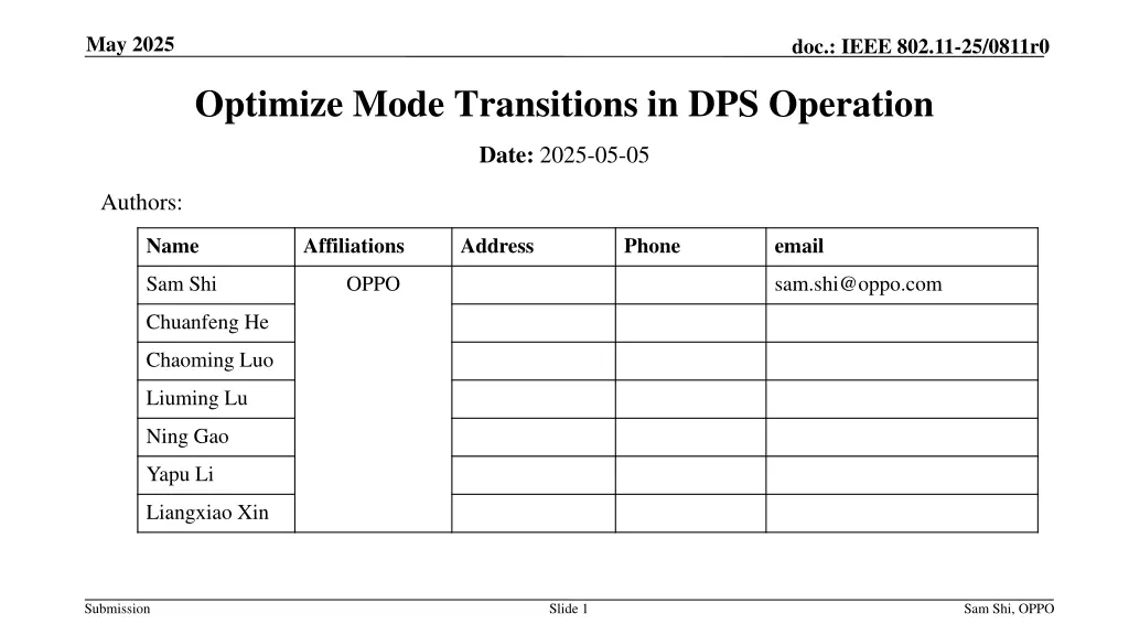
May 2025 doc.: IEEE 802.11-25/0811r0 Optimize Mode Transitions in DPS Operation Date: 2025-05-05 Authors: Name Affiliations Address Phone email Sam Shi OPPO sam.shi@oppo.com Chuanfeng He Chaoming Luo Liuming Lu Ning Gao Yapu Li Liangxiao Xin Submission Slide 1 Sam Shi, OPPO
May 2025 doc.: IEEE 802.11-25/0811r0 Introduction The UHR SG agreed to define a mechanism to reduce power consumption for Access Points (APs) (including mobile APs) and improved Peer-to-Peer (P2P) operation in UHR proposed PAR. A motion was approved stating that: TGbn defines a power save mode for a STA that is a UHR Mobile AP or a UHR non-AP STA wherein the STA may transition from a lower capability mode to a higher capability mode upon reception of an initial control frame. Discussions on AP power save (PS) and dynamic power save (DPS) have focused on several key aspects [1-9] Lower capability mode (e.g., 20 MHz BW, one SS, limited data rates, PPDU format) Higher capability mode (e.g., 40+ MHz BW, NSS and MCSs) Design and selection of Initial Control Frame (ICF) and Initial Control Response (ICR) Coexistence with other features, such as MLO and NPCA Protection mechanism of higher capability mode etc. Submission Slide 2 Sam Shi, OPPO
May 2025 doc.: IEEE 802.11-25/0811r0 Background Several contributions have highlighted that transitioning between lower and higher capability mode, especially involving channel bandwidth change, can be time-consuming, at hundreds of microseconds [10]. As shown in the figure below, it is not optimal for a DPS non-AP STA to transition to a lower capability mode when additional DL data at the AP is pending for transmission. Only part of data complete transmission ICF with padding DL Data ICF with padding DL Data DPS assisting AP Padding delay Padding delay Transition delay Transition delay DPS non-AP STA ICR BA ICR BA Lower capability mode Higher capability mode Lower capability mode Higher capability mode TXOP ends TXOP ends A DPS assisting AP has DL data for a DPS non-AP STA. The AP uses ICF to bring the STA to higher capability mode but only transmits part of the data e.g. due to a limited TXOP duration. The STA then transitions back to lower capability mode while waiting for next TXOP. The AP again uses ICF to bring the STA to higher capability mode for data transmission. The above steps may repeat till all data complete transmission This results in redundant mode transitions, which introduces unnecessary latency and inefficiency. Also, the intended power saving is not significant as frequent mode switch consumes extra power. Submission Slide 3 Sam Shi, OPPO
May 2025 doc.: IEEE 802.11-25/0811r0 Background Previous studies [11] have proposed higher capability protection mechanisms in DPS to reduce frequent capability state transitions and avoid unnecessary time, padding, and power overhead before the completion of data transmission. This approach is promising by providing a buffer period before a STA transitions back to lower capability mode. A protection timer is introduced allowing a DPS STA to remain in higher capability mode. The timer value is explicitly signaled in each ICF/ICR and can be dynamically adjusted as needed. The protection timer-based solution requires the timer field to be present in every ICF and ICR. Consequently, it mandates ICF and ICR exchange for every transmission, even when the STA is already operating in higher capability mode, potentially introducing signaling overhead. Submission Slide 4 Sam Shi, OPPO
May 2025 doc.: IEEE 802.11-25/0811r0 Proposal 1 explicit data indicator (DL) Proposal 1: Use of explicit data indicator for sustaining higher capability mode Example scenario: downlink (DL) data from a DPS assisting AP to a DPS non-AP STA The DPS assisting AP uses ICF to bring the DPS non-AP STA to higher capability mode. The AP uses a data indicator to inform the STA that additional DL data is pending. This indicator can be defined and transferred through various mechanisms: further methods can be discussed. In this example, the indicator is embedded in the DL data PPDU. Upon receiving the indicator with value of '1', the STA remains in higher capability mode, avoiding unnecessary mode transitions are prevented. DL Data (Indicator = 1) DL Data (Indicator = 0) ICF with padding DPS assisting AP Padding delay Transition delay DPS non-AP STA BA BA ICR Lower capability mode Higher capability mode Lower capability mode TXOP ends TXOP ends Submission Slide 5 Sam Shi, OPPO
May 2025 doc.: IEEE 802.11-25/0811r0 Proposal 1 explicit data indicator (UL) Example scenario: uplink (UL) data from a DPS assisting non-AP STA to a DPS mobile AP The DPS assisting non-AP STA uses ICF to bring the DPS mobile AP to higher capability mode. The STA uses a data indicator to inform the mobile AP that additional UL data is pending. Like the DL case, details of the indicator can be further defined. In this example, the indicator is embedded in the UL data PPDU. Upon receiving the indicator with value of '1', the mobile AP remains in higher capability mode avoiding unnecessary mode transitions. TXOP ends TXOP ends Lower capability mode Higher capability mode Lower capability mode Transition delay ICR BA BA Padding delay DPS mobile AP UL Data (Indicator = 1) UL Data (Indicator = 0) DPS assisting non-AP STA ICF with padding In a light traffic channel environment, where APs can acquire TXOPs in quick succession, staying in higher capability mode longer is more efficient in both latency and power consumption. Submission Slide 6 Sam Shi, OPPO
May 2025 doc.: IEEE 802.11-25/0811r0 Proposal 2 guard timer In some cases, after a data indicator is set to 1, no additional data arrives or a TXOP is not acquired. To prevent the AP or STA from remaining in higher capability mode unnecessarily, a guard timer mechanism is proposed. Proposal 2: use of guard timer to avoid unnecessary prolonged higher capability mode. This mechanism is only applicable when data indicator is set to 1. The timer is managed in a lightweight manner: It does not need to be configured in ICF/ICR. It can be configured during DPS preparation phase or at other occasions (TBD). If the guard timer expires, the device transitions back to lower capability mode. The exact rules for when to start, restart, or stop the timer can be further defined. Submission Slide 7 Sam Shi, OPPO
May 2025 doc.: IEEE 802.11-25/0811r0 Summary It is important to keep a non-AP STA or a mobile AP in higher capability mode when additional data is pending to avoid unnecessary delays caused by repeated mode transitions. The previously proposed protection timer is a promising solution [11] , but it may require further refinement and optimization. Proposal 1: use of explicit data indicator for sustaining higher capability mode. Proposal 2: use of guard timer to avoid unnecessary prolonged higher capability mode. This mechanism is only applicable when data indicator is set to 1. Submission Slide 8 Sam Shi, OPPO
May 2025 doc.: IEEE 802.11-25/0811r0 References [1] 11-23/10r0, Considerations for enabling AP power save , Alfred Asterjadhi et al. [2] 11-23/15r0, AP MLD power management , Liwen Chu, et al. [3] 11-23/225r0, Considering unscheduled AP power save , Guogang Huang et al. [4] 11-23/244r1, AP Power Save PAR addition proposal , Amelia Andersdotter, et al. [5] 11-23/1875r1, Power save proposal for non-AP/mobile AP , Sindhu Verma et al. [6] 11-23/1965r2, Dynamic Power Save - follow up , George Cherian et al. [7] 11-23/2003r1, Client-power-save , Laurent Cariou et al. [8] 11-24/451r0, AP state transitions in DPS mode , Vishnu V. Ratnam et al. [9] 11-24/833r0, Dynamic Power Saving for AP , Geonhwan Kim et al. [10] 11-24/844r0, Padding Time in Dynamic Power Save , Maolin Zhang et al. [11] 11-24/2080r1, High-Capability Protection in DPS Follow Up , Maolin Zhang et al. [12] 11-24/171r26, TGbn Motions List - Part 1 , Alfred Asterjadhi. Submission Slide 9 Sam Shi, OPPO
May 2025 doc.: IEEE 802.11-25/0811r0 Straw Poll Straw Poll 1: Do you support to define an explicit data indicator for sustaining higher capability mode? Straw Poll 2: If an explicit data indicator is defined, do you support to define a guard timer to avoid unnecessary prolonged higher capability mode? Submission Slide 10 Sam Shi, OPPO


