PCB Thermal Design with Ultra Small Flip-Chip Packages

Introducing thermal management techniques for PCBs featuring ultra small flip-chip packages, exploring heat transfer theories, comparing different package types, and optimizing thermal resistance paths.

Download Presentation

Please find below an Image/Link to download the presentation.
The content on the website is provided AS IS for your information and personal use only. It may not be sold, licensed, or shared on other websites without obtaining consent from the author.If you encounter any issues during the download, it is possible that the publisher has removed the file from their server.
You are allowed to download the files provided on this website for personal or commercial use, subject to the condition that they are used lawfully. All files are the property of their respective owners.
The content on the website is provided AS IS for your information and personal use only. It may not be sold, licensed, or shared on other websites without obtaining consent from the author.
E N D
Presentation Transcript
PCB Thermal Design with ultra small flip-chip packages (without Thermal Pad): HotRod Arief Hernadi - Application Engineer CCP (APP, BSR) With material provided by Frank De Stasi, Marc-Davis Marsh, Anthony Fagnani 1
Arief Hernadi Application Engineer, CCP Career Masters in Electrical Engineering, Cal Poly San Luis Obispo Applications Engineer (>5 years) Expertise DC-DC Converter EMI PCB Layout Photography 2 2
Agenda 1. Thermal Design Primer Goal Thermal Management Thermal Design Terminology 2. Hot Rod Package Benefit of Hot Rod Package Comparing Hot-Rod and Standard Wirebond QFN Package 3. Designing a PCB for best Performance Estimating Board Copper Size Layout a Hot-Rod Package Thermal Vias 4. Example of LMR33630 SOIC and Hot Rod Package Evaluating Thermal performance of both package in a given design 3
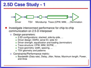
Heat Transfer IC Power Loss is Heat Conduction or diffusion: The transfer of energy between objects that are in physical contact The primary path for heat leaving the IC package Convection: The transfer of energy between an object and its environment, due to fluid motion The primary path for heat leaving the PCB Radiation: The transfer of energy to or from a body by means of the emission or absorption of electromagnetic radiation The secondary path for heat leaving the PCB and the IC package Goal: provide minimum resistance path for heat flow Minimum IC temp rise 5
Heat transfer basic theory k A T Conduction: = Q Dominant L Convection: = h A Q T ( ) Radiation: 4 b 4 a = Q A T T Where: Q = heat k = material conductivity A = area L = thickness (length) h = convection coefficient T = temperature delta = emissivity = Stefan-Boltzmann constant 6
Analogy Between Thermal and Electrical Resistance Electrical => Q is Charge Thermal => Q is Heat
Thermal 101 Thermal Design 101 Typical Values CU 71.4 C/W Based on 1oz copper, W=1cm L=1cm. CU= 4 W/cm K VIA 261 C/W Based on 0.5oz plating thickness, for 300um via (12mil) http://www.ti.com/lit/an/snva419c/snva419c.pdf FR4 13.9 C/W Based on 320um thickness, W=1cm L=1cm. FR4=0.0023 W/cm K SA 1000 C/W W=1cm L=1cm. h= 0.001 W/cm K 8
Thermal Design Terminology Thermal Design Terminology At each interface from the junction to the ambient air there is an associated thermal resistance 9
The Goal of Thermal Management Power dissipation of converter. Depends on required output power and converter efficiency Maximum junction temperature. Given in data sheet of converter; usually 125 C or 150 C = + T T P J A D JA Thermal resistance from ambient to junction of converter. Depends on everything; package, copper area, airflow, etc. Maximum ambient temperature. Specified by customer application The goal is to keep TJ below the maximum specified in the data sheet. 10
Some Basic Terminology Thermal resistance; JA Total thermal resistance from the junction to the ambient environment Not too easy to estimate, in some cases Depends on many factors Package type Copper heatsink area Air flow Number of copper planes Weight of copper planes Number of thermal vias Adjacent components Power dissipation 11
Some Basic Terminology Difference between -type and -type Parameters Type All the heat flows from the junction to location X Assumes isothermal conditions Location X serves as the external heat sink to the package Assumes non-isothermal conditions Type Only a fraction of the heat flows from the junction to location X Assumes non-isothermal conditions Temperature gradient exists in location X Assumes non-isothermal conditions
JT vs JC Power dissipation = 2 W Case temp monitor Cu Plate at constant temp =25 C 0.1 W 2 W Junction temp monitor 0.8 W Chip Chip Pad Pad PWB PWB 1.1 W Theta JC Psi-JT T T All the Power is forced to be dissipated only in one direction {UPWARD} = Junc Case JC Power Power is dissipated in all directions T T = Junc case jt Power T C P J B A J B A
Comparing Hotrod Package and Wirebond Package HotRod Minimize EMI through: 1. No-wirebond VSON packaging 2. Symmetric pinout 3. Spread spectrum feature Flip chip on lead frame QFN Standard wirebond QFN package Silicon die copper bump solder lead frame board Wirebond Silicon die lead frame board Die is flipped and placed directly onto the lead frame More ringing Less ringing
Package Differences Exposed Thermal DAP HotRod QFN Bondwires connect IC to pins Good thermal performance Higher parasitic resistance and inductance Larger than QFN Copper pillars (bumps/posts) on IC soldered directly to the lead-frame Poor thermals, compared to DAP Reduced parasitic resistance and inductance Smaller than SOIC Heat flow Heat flow 16
Thermal Path for Exposed Pad Packages PowerPad QFP/TSSOP, QFN Typical power: 0.5-10W Thermal design for these packages: Soldered to PCB thermal/GND plane PCB has thermal pad and vias tied to ground plane Most of the Heat uses the Exposed Pad, because that is the lowest thermal impedance path <1% ~20% ~80%
Thermal Path for HotRod Flipped Die on Lead Frame (HotRod ) Typical power: 0.5-3W Thermal design for these packages: Large Pads connected to Power Devices are essential to distribute heat. Most of Heat is through large pads because of metal routing but pins can also distribute heat PGND, GND, SW: Most effective <2% ~98% ~98%
Thermal Layout for HotRod Fat and Wide Traces on VIN, GND, SW NOTE: Tradeoff on SW pin for EMI and Thermal Lots of GND vias
Thermal Characteristics Table in Data Sheet HotRod SOIC Values of JA given in the table are NOT useful for thermal design They are useful for comparing packages within TI or with our competitors The other values can be useful JC , JB and JT are the most useful
Thermal Characteristics Table in Data Sheet The values given in the table are simulations The traces on the JEDEC board are too small to provide adequate heat-sinking For HotRod the heat is mostly dissipated from the pads This makes the JEDEC board a bad estimate for thermals JEDEC uses the same standard for all packages This makes the numbers good for comparing packages Need better methods for estimating JA
Design Strategy Summary 1. Calculate PD based on the efficiency and system inputs: TA, VIN, VOUT, IOUT Calculate required JA 2. 3. Determine required board size Datasheet guidelines SNVA419C spreadsheet Online calculator WebTHERM /Webench 4. Follow Layout Guidelines for vias, and routing, etc. 23
Example: Scenario: Customer: I have this input voltage, output voltage, output current and ambient temperature Is it going to work OK thermally? How much board space/heat sinking do I need with this device? Step 1: Estimate the IC power dissipation. Step 2: Determine Thermal Requirements Step 3: Determine Board Size Based on Thermal Requirements 24
Step 1. Estimate the IC Power Dissipation 1a. Look in the datasheet for an efficiency curve that is close to the given application conditions. Ideally the efficiency should be taken at a temperature greater than 25 C, since the die will always be above ambient when running with load. 1 = LOSS P OUT V OUT I 1b. Calculate the total power loss using: 2 OUT I = 1c. Subtract the loss in the inductor to get the IC PD: P LOSS P R D L = R Inductor DCR L 25
Step 1. (cont.) LMR33630 RNX (Hot Rod) VIN = 12V, VOUT, = 5V, IOUT = 3A, 2.1MHz Example: 1a. We find an efficiency from the data sheet: Approximate Efficiency of 91% based on graph shown 1b. PLOSS = 1.48W 1c. PD = 1.16W (RL~35m from EVM user guide) 26
Step 2. Calculate maximum allowable JA For this step we need the maximum ambient temperature from the application requirement and the maximum junction temperature from the data sheet. TA = 85 C TJmax = 150 C Jmax T T A JA P D We get JA 56 C/W A quick start calculator is also available to help with what-if calculations: 27
Step 3. Estimate the PCB Copper Area OPTIONS: A. Datasheet JA vs Copper Area Curves (Easiest Option if available) B. Thermal Estimate Based Excel Calculator C. PCB Thermal Calculator online or other simulation tools D. Webench Thermal Simulation 28
Step 3: Option A Data Sheet Curves This option is more accurate since it based on measured data. The curves for LMR33630 are shown below: This curve indicates that a 4 layer board with an area of 4.0 cm x 5.0 cm (20 cm2) will give JA < 56 C/W 29
Step 3: Option B Thermal Estimator Excel Application Note SNVA419C and the associated spread-sheet can be used to estimate the required board size for a given set of conditions Allows you to play what-if scenarios Works well for packages with a DAP Need to adjust values of JC for other package types AN-2020 Thermal Design By Insight, Not Hindsight : http://www.ti.com/lit/an/snva419c/snva419c.pdf 30
Step 3: Option C Online PCB Calculator Only available for some IC packages http://www.ti.com/adc/docs/midlevel.tsp?contentId=76735 31
Step 3: Option D Webench / WebTHERM https://webench.ti.com/webench5/power/webench5.cgi 32
Step 3: Data Sheet De-Rate Curves Many data sheets will have a de-rating curve This shows the maximum load current for a given ambient temperature Taken with one particular JA Uses the efficiency taken at an elevated temperature 85 C or 125 C 34
Effects of Copper Area (TPS54824) Comparing the 2 different copper area, at higher current of 8A, the improvement of case temperature ~ 10 C App Note: http://www.ti.com/lit/an/snva839/snva839.pdf 35
Step 4: Layout Guidelines Copper Thickness Use appropriate copper thickness 1oz copper thickness is 35 m and 2 oz copper thickness is 70 m At least 1 oz copper is recommended for all DC-DC converter designs. 2 oz copper is recommended for designs that dissipate more than 3 Watts Example: For a copper area of 3 inches x 3 inches: 1 oz copper : JA ~ 28 C/W 2 oz copper : JA ~ 21 C/W About 25% improvement 1 Length CU CU = Width Thickness 36
Ambient Air Temperature (TA) Step 4: Layout Guidelines Vias SA Junction Temperature TJ __ SA SA SA JC TC Use lots of vias Thermal resistances in parallel The more you add, the lower the resistance is. Cu Cu Cu FR4 FR4 FR4 FR4 Cu Cu Cu Cu Cu FR4 FR4 FR4 FR4 VIA Cu Cu Cu Cu Typical 0.3mm (12mil) thermal vias with 17.5 m (0.5oz) plating 1.56mm (62mil) PCB thickness SA FR4 FR4 FR4 FR4 Cu Cu Cu Cu Cu SA SA SA SA SA 251 vias no.of vias Via Array Thermal Resistance Calculations: More thermal via guidelines in Application Notes SNVA419C and AN-1520 37
Step 4: Layout Guidelines Cuts in Copper Planes - Cut copper plane parallel to heat flow 115C 121C 117C 38 38
Step 4: Layout Guidelines Pizza Slice 1. 2. IC is the heat source and tiny compared to PCB Maximize so that heat is radiating in all 360 degree directions of top and bottom copper plane Ideally, heat source is placed in center of a PCB If the tip of the slice is not touching the heat source properly then the whole slice can not efficiently contribute as heat sink Make thermal cuts only in heat flow directions Maximize total copper area, number of layers and Cu thickness on PCB Utilize the bottom copper side of PCB Use all available external components like Inductors, resistors and ceramic caps as potential heat conductors to bridge to colder areas / slices Use larger components like connectors and aluminum caps to improve heat sinking of slices 3. 4. 5. 6. 7. 8. 9. 39
Step 4: Layout Guidelines Optimum Cuts Non-optimized PCB design Die Temp = 124 C JA = 32 C/W Thermally Optimized PCB Die Temp = 88.3 C JA = 20.4 C/W Large Copper Slices GND SW GND VIN AGND Thermal Bottlenecks 40
Step 4: Layout Guidelines High Current Vias High Current Via Requirements: 1A/via max <14mil diameter 2A/via max >14 mil diameter 5A/via max >40 mil diameter Don t block high current paths with vias 41
Step 4: Example of vias near the IC (TPS54824) REV A REV B App Note: http://www.ti.com/lit/an/snva839/snva839.pdf 42
Step 4: Via Density near the IC App Note: http://www.ti.com/lit/an/snva839/snva839.pdf 43
Other Considerations Thermal Coupling & Footprint Thermal Coupling Devices in a system are always thermally coupled Most significant when packages get closer than 2x the package dimension to each other Device Thermal Footprint Thermal Footprint A thermal footprint is the area of the PCB that participates strongly in the convection and radiation from the package This area is about 18x the package area as shown Top of PCB and bottom of PCB count Thermal Coupling When thermal footprints overlap, changes in junction temperatures are dramatic Max T = 69.8 C
Other Considerations Thermal Coupling Example Separation=25mm Max T = 84.4 Separation=50mm Max T = 81.6 C C Separation=8mm Max T = 98.4 Separation=12.5mm Max T = 92.9 C C
Which Thermal Performance is BETTER? Inductor 74438335150 (3mm x 3mm x 1.5mm) 15 H, 720m Inductor XAL4040-153 (4mm x 4mm x 4mm) 15 H, 84m 46
TEMPERATURE COMPARISON Operating Conditions LMR36015 VIN = 24V VOUT = 5V IOUT = 1.2A Switching frequency = 2.1MHz IC Package Temperature ~ 71 C IC Package Temperature ~ 92 C = 21 C 47
Some Layout Best Practices Spread out hot devices on PCB Maximize GND layer in PCB No breaks in heat flow through planes Increase PCB layers or thickness Widen PCB traces near device Thermal vias under or near device Airflow (global and local)
Quizlayout review COUT L CIN CIN LM53625 2.5A Synchronous Buck Converter 2.1MHz 49
Question: Will 5A converter always support 5A? Answer: It depends . Ambient Temperature Efficiency /Power Loss Board Size Thermal Shutdown ? R JA VIN = 12V and VOUT = 5V IOUT = 2 x 2.1A (4.2A Total), Ta = 22 deg C EXAMPLE DUAL USB DESIGN: Will this work at 125 degree C ambient? http://www.ti.com/lit/ug/tiducz9/tiducz9.pdf 50


 Package")


")


")


")