Pipelining in MIPS: Enhancing Hardware Utilization
Explore the concept of pipelining in MIPS architecture to parallelize operations and optimize hardware efficiency. Learn about spatial and temporal parallelism, definitions related to parallelism, and a practical example of baking cookies to understand latency and throughput benefits. Discover the advantages of using parallelism to improve system performance.

Download Presentation

Please find below an Image/Link to download the presentation.
The content on the website is provided AS IS for your information and personal use only. It may not be sold, licensed, or shared on other websites without obtaining consent from the author. If you encounter any issues during the download, it is possible that the publisher has removed the file from their server.
You are allowed to download the files provided on this website for personal or commercial use, subject to the condition that they are used lawfully. All files are the property of their respective owners.
The content on the website is provided AS IS for your information and personal use only. It may not be sold, licensed, or shared on other websites without obtaining consent from the author.
E N D
Presentation Transcript
COMP541 Pipelined MIPS Montek Singh Apr 24, 2017 1
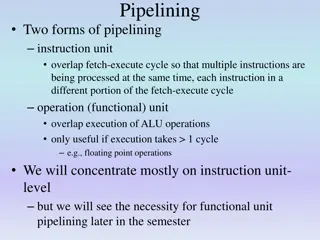
Topics Today s topic: Pipelining Can think of it as: A way to parallelize, or A way to make better utilization of the hardware. Goal: Try to use all hardware every clock cycle Reading Section 7.5 of textbook 2
Parallelism Two types of parallelism: Spatial parallelism duplicate hardware performs multiple tasks at once Temporal parallelism overlapping execution of successive instructions task is broken into multiple stages each stage operating on different parts of distinct instructions also called pipelining example: an assembly line 3
Parallelism Definitions Some definitions: Token: A group of inputs processed together to produce a group of outputs a bundle an instruction is a token Latency: Time for one token to pass from start to end Throughput: Number of tokens processed per unit time Parallelism increases throughput Often sacrificing latency Why? 4
Parallelism Example: Baking Cookies! Ben is baking cookies 2-part task: It takes 5 minutes to roll the cookies and 15 minutes to bake them After finishing one batch he immediately starts the next batch. What is the latency and throughput if Ben does NOT use parallelism? Latency = 5 + 15 = 20 min = 1/3 hour Throughput = 1 tray/ 20 min = 3 trays/hour 5
Parallelism Example: Baking Cookies! What is the latency and throughput if Ben uses parallelism? Spatial parallelism: Ben asks Allysa to help, using two ovens/kitchens instead of one. Temporal parallelism: Ben breaks the task into two stages: roll and baking. He uses two trays. While the first batch is baking he rolls the second batch, and so on. 6
Baking Cookies: Spatial Parallelism Latency: time to first tray 0 5 10 15 20 25 30 35 40 45 50 Time Tray 1 Ben 1 Ben 1 Roll Parallelism Tray 2 Alyssa 1 Alyssa 1 Spatial Bake Tray 3 Ben 2 Ben 2 Legend Tray 4 Alyssa 2 Alyssa 2 Latency = ? Throughput = ? 7
Baking Cookies: Spatial Parallelism Latency: time to first tray 0 5 10 15 20 25 30 35 40 45 50 Time Tray 1 Ben 1 Ben 1 Roll Parallelism Tray 2 Alyssa 1 Alyssa 1 Spatial Bake Tray 3 Ben 2 Ben 2 Legend Tray 4 Alyssa 2 Alyssa 2 Latency = 5 + 15 = 20 min = 1/3 hour (same) Throughput = 2 trays/ 20 min = 6 trays/hour (doubled) 8
Baking Cookies: Temporal Parallelism Latency: time to first tray 0 5 10 15 20 25 30 35 40 45 50 Time Tray 1 Ben 1 Ben 1 Parallelism Temporal Tray 2 Ben 2 Ben 2 Tray 3 Ben 3 Ben 3 Latency = ? Throughput = ? Note: This scenario assumes each step is performed as soon as a resource is available. Latency will be lower if rolling is started as late as possible. 9
Baking Cookies: Temporal Parallelism Latency: time to first tray 0 5 10 15 20 25 30 35 40 45 50 Time Tray 1 Ben 1 Ben 1 Parallelism Temporal Tray 2 Ben 2 Ben 2 Tray 3 Ben 3 Ben 3 Latency = 5 + 15 = 20 min = 1/3 hour Throughput = 1 trays/ 15 min = 4 trays/hour Cost? An extra tray Using both types of parallelism together, the throughput would be 8 trays/hour 10
Another example: Laundry Laundry Example: Ann, Brian, Cathy, Dave each have one load of clothes to wash, dry, and fold A B C D Washer takes 30 minutes Dryer takes 40 minutes Folding takes 20 minutes 11
Sequential Laundry 6 PM Midnight 7 8 9 11 10 Time 30 40 20 30 40 20 30 40 20 30 40 20 T a s k A B O r d e r C D Sequential laundry takes 6 hours for 4 loads With pipelining, how long would laundry take? 12
Pipelined Laundry ?? 6 PM Time T a s k A B O r d e r C D Pipelined laundry takes ?? hours for 4 loads 13
Pipelined Laundry 6 PM Midnight 7 8 9 11 10 Time 30 40 40 40 40 20 T a s k A B O r d e r C D Pipelined laundry takes 3.5 hours for 4 loads 14
Pipelining Principles Pipelining doesn t help latency of single task, it helps throughput of entire workload 6 PM 7 8 9 Time Pipeline rate limited by slowest pipeline stage 30 40 40 40 40 20 Multiple tasks operating simultaneously T a s k A Potential speedup = Number pipe stages B O r d e r Unbalanced stage delays reduces speedup C Time to fill pipeline and to drain it reduces speedup D can be ignored for very large number of laundry loads 15
Pipelined MIPS Temporal parallelism Divide single-cycle processor into 5 stages: Fetch Decode Execute Memory Writeback Add pipeline registers between stages sort of like extra cookie trays 16
Pipelined MIPS Divide single-cycle processor into 5 stages: Fetch (IF) / Decode (ID) / Execute (EX) / Memory (MEM) / Writeback (WB) Decode Execute Memory Write-Back Fetch 17
Single-Cycle vs. Pipelined Performance Pipelining Break instruction into 5 steps Each is 250 ps long (length of longest step) Single-Cycle 0 100 200 300 400 500 600 700 800 900 1000 1100 1200 1300 1400 1500 1600 1700 1800 1900 Instr Time (ps) Fetch Instruction Execute ALU Memory Read / Write Write Reg Decode Read Reg 1 Fetch Instruction Execute ALU Memory Read / Write Write Reg Decode Read Reg 2 Pipelined Write Reg and Read Reg occur during the first half and second half of the clock cycle, respectively. This allows more instruction overlap! Instr Fetch Instruction Execute ALU Memory Read/Write Write Reg Decode Read Reg 1 Fetch Instruction Execute ALU Memory Read/Write Write Reg Decode Read Reg 2 Fetch Instruction Execute ALU Memory Read/Write Write Reg Decode Read Reg 3 18
Pipelining Abstraction 5 stages of execution instruction memory (fetch) register file read ALU/execution data memory access register file write (writeback) 1 2 3 4 5 6 7 8 9 10 Time (cycles) $0 $s2 lw DM lw $s2, 40($0) IM RF 40 RF + $t1 $s3 add DM add $s3, $t1, $t2 IM RF $t2 RF + $s1 $s4 sub DM sub $s4, $s1, $s5 IM RF $s5 RF - $t5 $s5 and DM and $s5, $t5, $t6 IM RF $t6 RF & $s1 $s6 sw DM sw $s6, 20($s1) IM RF 20 RF + $t3 $s7 or DM or $s7, $t3, $t4 IM RF $t4 RF | 19
Single-Cycle and Pipelined Datapath Key difference: insertion of pipeline registers CLK CLK CLK WE3 Zero WE SrcA 25:21 0 1 A1 RD1 PC' PC Instr 0 1 A Instruction Memory RD ALUResult ReadData ALU A RD 20:16 A2 RD2 0 1 SrcB Data Memory WD A3 WD3 WriteData Register File 20:16 0 1 WriteReg4:0 15:11 PCPlus4 + SignImm 4 <<2 15:0 Sign Extend PCBranch + Result CLK CLK ALUOutW CLK CLK CLK CLK CLK WE3 WE ZeroM SrcAE 25:21 0 1 A1 RD1 PC' PCF InstrD 0 1 A Instruction Memory RD ALU ReadDataW ALUOutM A RD 20:16 A2 RD2 0 1 SrcBE Data Memory WD A3 WD3 WriteDataM Register File WriteDataE RtE 20:16 0 1 WriteRegE4:0 RdE 15:11 + SignImmE 4 <<2 15:0 PCBranchM Sign Extend + PCPlus4F PCPlus4D PCPlus4E ResultW 20 Fetch Decode Execute Memory Writeback
Multi-Cycle and Pipelined Datapath Key difference: full-length registers for datapath and control CLK CLK MemtoReg RegDst CLK CLK CLK CLK CLK CLK WE3 Zero 0 WE SrcA SrcA 25:21 0 1 A1 25:21 RD1 PC' PC Instr CLK 0 1 WE WE3 Zero A B A Instruction Memory Instr / Data Memory WD RD RD ALUResult 1 ReadData ALUResult ALU A1 A2 RD1 PC' PC Instr 0 1 A RD 0 1 Adr ALU 20:16 ALUOut A RD2 00 01 10 11 20:16 A2 RD2 0 1 SrcB EN EN Data Memory WD 4 A3 WD3 15:11 SrcB 20:16 WriteData 0 Register File 1 A3 Register File CLK 20:16 0 1 WriteReg4:0 0 1 Data WD3 15:11 PCPlus4 <<2 + SignImm 4 <<2 15:0 Sign Extend PCBranch SignImm + 15:0 Sign Extend Result CLK CLK ALUOutW CLK CLK CLK CLK CLK WE3 WE ZeroM SrcAE 25:21 0 1 A1 RD1 PC' PCF InstrD 0 1 A Instruction Memory RD ALU ReadDataW ALUOutM A RD 20:16 A2 RD2 0 1 SrcBE Data Memory WD A3 WD3 WriteDataM Register File WriteDataE RtE 20:16 0 1 WriteRegE4:0 RdE 15:11 + SignImmE 4 <<2 15:0 PCBranchM Sign Extend + PCPlus4F PCPlus4D PCPlus4E ResultW 21 Fetch Decode Execute Memory Writeback
CLK CLK CLK One Problem WE3 Zero WE SrcA 25:21 0 1 A1 RD1 PC' PC Instr 0 1 A Instruction Memory RD ALUResult ReadData ALU A RD 20:16 A2 RD2 0 1 SrcB Data Memory WD A3 WD3 WriteData Register File There is a problem: mismatched paths Result to write back and reg des are out of step 20:16 0 1 WriteReg4:0 15:11 PCPlus4 + SignImm 4 <<2 15:0 Sign Extend PCBranch + Result CLK CLK ALUOutW CLK CLK CLK CLK CLK WE3 WE ZeroM SrcAE 25:21 0 1 A1 RD1 PC' PCF InstrD 0 1 A Instruction Memory RD ALU ReadDataW ALUOutM A RD 20:16 A2 RD2 0 1 SrcBE Data Memory WD A3 WD3 WriteDataM Register File WriteDataE RtE 20:16 0 1 WriteRegE4:0 RdE 15:11 + SignImmE 4 <<2 15:0 PCBranchM Sign Extend + PCPlus4F PCPlus4D PCPlus4E ResultW Fetch Decode Execute Memory Writeback 22
Corrected Pipelined Datapath Solution: One modification needed Keep result and reg dest together both go through equal number of pipeline stages The belong together as a single token CLK CLK ALUOutW CLK CLK CLK CLK CLK WE3 WE ZeroM SrcAE 25:21 0 1 A1 RD1 PC' PCF InstrD 0 1 A Instruction Memory RD ALU ReadDataW ALUOutM A RD 20:16 A2 RD2 0 1 SrcBE Data Memory WD A3 WD3 WriteDataM Register File WriteDataE RtE 20:16 0 1 WriteRegE4:0 WriteRegM4:0 WriteRegW4:0 RdE 15:11 SignImmE + <<2 15:0 Sign Extend PCBranchM 4 + PCPlus4F PCPlus4D PCPlus4E ResultW Fetch Decode Execute Memory Writeback 23
Pipelined Control What is similar/different w.r.t. single-cycle MIPS? Same control signal values Values must be delayed and delivered in correct cycles Control signals must go through registers as well! Token = data + control! CLK CLK CLK RegWriteE RegWriteM RegWriteW RegWriteD Control Unit MemtoRegE MemtoRegM MemtoRegW MemtoRegD MemWriteE MemWriteM MemWriteD BranchE BranchM BranchD 31:26 PCSrcM Op ALUControlE2:0 ALUControlD 5:0 Funct ALUSrcD ALUSrcE RegDstD RegDstE ALUOutW CLK CLK CLK CLK WE3 WE ZeroM SrcAE 25:21 0 1 A1 RD1 PC' PCF InstrD 0 1 A Instruction Memory RD ALU ReadDataW ALUOutM A RD 20:16 A2 RD2 0 1 SrcBE Data Memory WD A3 WD3 WriteDataM Register File WriteDataE RtE 20:16 0 1 WriteRegE4:0 WriteRegM4:0 WriteRegW4:0 RdE 15:11 + <<2 15:0 Sign Extend SignImmE PCBranchM 4 + PCPlus4F PCPlus4D PCPlus4E 24 ResultW
Pipelining Challenges Hazards when an instruction depends on results from previous instruction that has not yet completed 2 types of hazards: Data hazard: register value not written back to register file yet an instruction produces a result needed by next instruction new value will be stored during write-back stage new value needed by next instr during register read following too close behind! Control hazard: don t know which is next instruction next PC not decided yet cause by conditional branches cannot fetch next instr if current branch is not yet decided 25
Data Hazard: Example First instruction computes a result ($s0) needed by the next 3 instructions first two cause problems third actually does not! Why not? Register file written in first half of clock cycle, read in second half 1 2 3 4 5 6 7 8 Time (cycles) $s2 $s0 add DM add $s0, $s2, $s3 IM RF $s3 RF + $s0 $t0 and DM and $t0, $s0, $s1 IM RF $s1 RF & $s4 $t1 or DM or $t1, $s4, $s0 IM RF $s0 RF | $s0 $t2 sub DM sub $t2, $s0, $s5 IM RF $s5 RF - 26
Handling Data Hazards Static/compiler approaches: Insert nop s (no operations) in code at compile time Rearrange code at compile time Dynamic/runtime approaches: Forward data at run time data goes directly from producer to consumer Stall the consuming instruction at run time 27
Compile-Time Hazard Elimination Insert enough nops between dependent instrs Or re-arrange: move independent instructions up 1 2 3 4 5 6 7 8 9 10 Time (cycles) $s2 $s0 add DM add $s0, $s2, $s3 IM RF $s3 RF + nop DM nop IM RF RF nop DM nop IM RF RF $s0 $t0 and DM and $t0, $s0, $s1 IM RF $s1 RF & $s4 $t1 or DM or $t1, $s4, $s0 IM RF $s0 RF | $s0 $t2 sub DM sub $t2, $s0, $s5 IM RF $s5 RF - 28
Compile-Time Hazard Elimination Insert enough nops between dependent instrs Or re-arrange: move independent instructions up 1 2 3 4 5 6 7 8 9 10 Time (cycles) $s2 $s0 add DM add $s0, $s2, $s3 IM RF $s3 RF + nop xor DM nop xor $t6, $t7, $t8 IM RF RF nop xor nop xor $t9, $t6, $t10 DM IM RF RF $s0 $t0 and DM and $t0, $s0, $s1 IM RF $s1 RF & $s4 $t1 or DM or $t1, $s4, $s0 IM RF $s0 RF | $s0 $t2 sub DM sub $t2, $s0, $s5 IM RF $s5 RF - 29
Dynamic Approach: Data Forwarding Also known as register bypassing results are actually available even though not stored in reg. grab a copy and send where needed! extra hardware needed Note: forwarding actually not needed for sub. Why again? 1 2 3 4 5 6 7 8 Time (cycles) $s2 $s0 add DM add $s0, $s2, $s3 IM RF $s3 RF + $s0 $t0 and DM and $t0, $s0, $s1 IM RF $s1 RF & $s4 $t1 or DM or $t1, $s4, $s0 IM RF $s0 RF | $s0 $t2 sub DM sub $t2, $s0, $s5 IM RF $s5 RF - 30
Data Forwarding: from MEM stage CLK CLK CLK RegWriteE RegWriteM RegWriteW RegWriteD Control Unit MemtoRegE MemtoRegM MemtoRegW MemtoRegD MemWriteE MemWriteM MemWriteD ALUControlD2:0 ALUControlE2:0 31:26 Op ALUSrcD ALUSrcE 5:0 Funct RegDstD RegDstE PCSrcM BranchD BranchE BranchM CLK CLK CLK CLK X WE3 WE SrcAE ZeroM 25:21 0 1 A1 RD1 00 01 10 PC' PCF InstrD A Instruction Memory RD ALU ReadDataW ALUOutM A RD X 20:16 A2 RD2 0 1 00 01 10 SrcBE Data Memory WD A3 WD3 WriteDataM Register File WriteDataE 1 0 RsD RsE ALUOutW 25:21 RtD RtE 20:16 0 1 WriteRegE4:0 WriteRegM4:0 WriteRegW4:0 RdD RdE 15:11 SignImmD SignImmE Sign Extend + 15:0 4 <<2 + PCPlus4F PCPlus4D PCPlus4E PCBranchM ResultW RegWriteW ForwardBE ForwardAE RegWriteM Hazard Unit 31
Data Forwarding: from WriteBack if ((rsE != 0) AND (rsE == WriteRegM) AND RegWriteM) then ForwardAE = 10 else if ((rsE != 0) AND (rsE == WriteRegW) AND RegWriteW)) then ForwardAE = 01 else ForwardAE = 00 CLK CLK CLK RegWriteE RegWriteM RegWriteW RegWriteD Control Unit MemtoRegE MemtoRegM MemtoRegW MemtoRegD MemWriteE MemWriteM MemWriteD ALUControlD2:0 ALUControlE2:0 31:26 Op ALUSrcD ALUSrcE 5:0 Funct RegDstD RegDstE PCSrcM BranchD BranchE BranchM CLK CLK CLK CLK X WE3 WE SrcAE ZeroM 25:21 0 1 A1 RD1 00 01 10 PC' PCF InstrD A Instruction Memory RD ALU ReadDataW ALUOutM A RD X 20:16 A2 RD2 0 1 00 01 10 SrcBE Data Memory WD A3 WD3 WriteDataM Register File WriteDataE 1 0 RsD RsE ALUOutW 25:21 RtD RtE 20:16 0 1 WriteRegE4:0 WriteRegM4:0 WriteRegW4:0 RdD RdE 15:11 SignImmD SignImmE Sign Extend + 15:0 4 <<2 + PCPlus4F PCPlus4D PCPlus4E PCBranchM ResultW RegWriteW ForwardBE ForwardAE RegWriteM Hazard Unit 32
Data Forwarding Forward to Execute stage from either: Memory stage (MEM) or WriteBack (WB) stage Forwarding logic for ForwardAE: for instruction i in Execute stage: if the destination reg of instr i-1 matches source reg, then forward from Mem stage if the destination reg of instr i-2 matches source reg, then forward from WB stage logic equations: if ((rsE != 0) AND (rsE == WriteRegM) AND RegWriteM) then ForwardAE = 10 else if ((rsE != 0) AND (rsE == WriteRegW) AND RegWriteW) then ForwardAE = 01 else ForwardAE = 00 Forwarding logic for ForwardBE same, but replace rsE with rtE 33
Forwarding may not always work Example: Load followed immediately by R-type loads are harder to deal with because they need mem access! data cannot go backwards in time! need one extra cycle, compared to R-type instructions 1 2 3 4 5 6 7 8 Time (cycles) $0 $s0 lw DM lw $s0, 40($0) IM RF 40 RF + Trouble! $s0 $t0 and DM and $t0, $s0, $s1 IM RF $s1 RF & $s4 $t1 or DM or $t1, $s4, $s0 IM RF $s0 RF | $s0 $t2 sub DM sub $t2, $s0, $s5 IM RF $s5 RF - lw has a 2-cycle latency! 34
Stalling Stall for a cycle, then forward solves the Load followed by R-type problem 1 2 3 4 5 6 7 8 9 Time (cycles) $0 $s0 lw DM lw $s0, 40($0) IM RF 40 RF + $s0 $s0 $t0 and DM and $t0, $s0, $s1 IM RF $s1 RF $s1 RF & $s4 $t1 or or DM or $t1, $s4, $s0 IM IM RF $s0 RF | Stall $s0 $t2 sub DM sub $t2, $s0, $s5 IM RF $s5 RF - 35
Stalling Hardware lwstall = ((rsD == rtE) OR (rtD == rtE)) AND MemtoRegE StallF = StallD = FlushE = lwstall CLK CLK CLK RegWriteE RegWriteM RegWriteW RegWriteD Control Unit MemtoRegE MemtoRegM MemtoRegW MemtoRegD MemWriteE MemWriteM MemWriteD ALUControlD2:0 ALUControlE2:0 31:26 Op ALUSrcD ALUSrcE 5:0 Funct RegDstD RegDstE PCSrcM BranchD BranchE BranchM CLK CLK CLK CLK WE3 WE SrcAE ZeroM 25:21 0 1 A1 RD1 00 01 10 PC' PCF InstrD A Instruction Memory RD ALU ReadDataW ALUOutM EN A RD 20:16 A2 RD2 0 1 00 01 10 SrcBE Data Memory WD A3 WD3 WriteDataM Register File WriteDataE 1 0 RsD RsE ALUOutW 25:21 RtD RtE 20:16 0 1 WriteRegE4:0 WriteRegM4:0 WriteRegW4:0 RdD RdE 15:11 SignImmD SignImmE Sign Extend + 15:0 4 <<2 + PCPlus4F PCPlus4D PCPlus4E CLR EN PCBranchM ResultW MemtoRegE RegWriteW ForwardBE ForwardAE RegWriteM FlushE StallD StallF Hazard Unit 36
Control Hazards beq: branch is not determined until the fourth stage of the pipeline Instructions after the branch are fetched before branch occurs These instructions must be flushed if the branch is taken 37
Effect & Solutions Could always stall until branch is completed Expensive: 3 cycles lost per branch! Could predict banch outcome, and flush if wrong Branch misprediction penalty Instructions flushed when branch is taken May be reduced by determining branch earlier 38
Control Hazards: Flushing Flushing turn instruction into a NOP (put all zeros) renders it harmless! 1 2 3 4 5 6 7 8 9 Time (cycles) $t1 lw DM 20 beq $t1, $t2, 40 IM RF $t2 RF - $s0 and DM 24 and $t0, $s0, $s1 IM RF $s1 RF & Flush these $s4 or DM instructions 28 or $t1, $s4, $s0 IM RF $s0 RF | $s0 sub DM 2C sub $t2, $s0, $s5 IM RF $s5 RF - 30 ... ... $s2 $t3 slt DM slt 64 slt $t3, $s2, $s3 IM RF $s3 RF 39
Control Hazards: Original Pipeline (for comparison) CLK CLK CLK RegWriteE RegWriteM RegWriteW RegWriteD Control Unit MemtoRegE MemtoRegM MemtoRegW MemtoRegD MemWriteE MemWriteM MemWriteD ALUControlD2:0 ALUControlE2:0 31:26 Op ALUSrcD ALUSrcE 5:0 Funct RegDstD RegDstE PCSrcM BranchD BranchE BranchM CLK CLK CLK CLK WE3 WE SrcAE ZeroM 25:21 0 1 A1 RD1 00 01 10 PC' PCF InstrD A Instruction Memory RD ALU ReadDataW ALUOutM EN A RD 20:16 A2 RD2 0 1 00 01 10 SrcBE Data Memory WD A3 WD3 WriteDataM Register File WriteDataE 1 0 RsD RsE ALUOutW 25:21 RtD RtE 20:16 0 1 WriteRegE4:0 WriteRegM4:0 WriteRegW4:0 RdD RdE 15:11 SignImmD SignImmE Sign Extend + 15:0 4 <<2 + PCPlus4F PCPlus4D PCPlus4E CLR EN PCBranchM ResultW MemtoRegE RegWriteW ForwardBE ForwardAE RegWriteM FlushE StallD StallF Hazard Unit 40
Control Hazards: Early Branch Resolution CLK CLK CLK RegWriteE RegWriteM RegWriteW RegWriteD Control Unit MemtoRegE MemtoRegM MemtoRegW MemtoRegD MemWriteE MemWriteM MemWriteD ALUControlD2:0 ALUControlE2:0 31:26 Op ALUSrcD ALUSrcE 5:0 Funct RegDstD RegDstE BranchD PCSrcD EqualD CLK CLK CLK CLK = WE3 WE SrcAE 25:21 0 1 A1 RD1 00 01 10 PC' PCF InstrD A Instruction Memory RD ALU ReadDataW ALUOutM EN A RD 20:16 A2 RD2 0 1 00 01 10 SrcBE Data Memory WD A3 WD3 WriteDataM Register File WriteDataE 1 0 RsD RsE ALUOutW 25:21 RtD RtE 20:16 0 1 WriteRegE4:0 WriteRegM4:0 WriteRegW4:0 RdE RdE 15:11 SignImmD SignImmE Sign Extend + 15:0 4 <<2 + PCPlus4F PCPlus4D CLR CLR EN PCBranchD ResultW MemtoRegE RegWriteW ForwardBE ForwardAE RegWriteM FlushE StallD StallF Hazard Unit Introduced another data hazard in Decode stage (fix a few slides away) 41
Control Hazards with Early Branch Resolution 1 2 3 4 5 6 7 8 9 Time (cycles) $t1 lw DM 20 beq $t1, $t2, 40 IM RF $t2 RF - $s0 Flush this instruction and DM 24 and $t0, $s0, $s1 IM RF $s1 RF & 28 or $t1, $s4, $s0 2C sub $t2, $s0, $s5 30 ... ... $s2 $t3 slt DM slt 64 slt $t3, $s2, $s3 IM RF $s3 RF Penalty now only one lost cycle 42
Aside: Delayed Branch MIPS always executes instruction following a branch So branch delayed This allows us to avoid killing next instruction Compilers move instruction that has no conflict w/ branch into delay slot 43
Example This sequence label: reordered to this label: add $4, $5, $6 beq $1, $2, label beq $1, $2, label add $4, $5, $6 The add is always executed! If branch is taken add is executed before the PC is set to the branch target If branch is not taken add is executed as the first instruction in follow-through 44
Handling the New Hazards CLK CLK CLK RegWriteE RegWriteM RegWriteW RegWriteD Control Unit MemtoRegE MemtoRegM MemtoRegW MemtoRegD MemWriteE MemWriteM MemWriteD ALUControlD2:0 ALUControlE2:0 31:26 Op ALUSrcD ALUSrcE 5:0 Funct RegDstD RegDstE BranchD PCSrcD EqualD CLK CLK CLK CLK = WE3 WE SrcAE 25:21 0 1 A1 RD1 0 1 00 01 10 PC' PCF InstrD A Instruction Memory RD ALU ReadDataW ALUOutM EN A RD 20:16 A2 RD2 0 1 0 1 00 01 10 SrcBE Data Memory WD A3 WD3 WriteDataM Register File WriteDataE 1 0 RsD RsE ALUOutW 25:21 RtD RtE 20:16 0 1 WriteRegE4:0 WriteRegM4:0 WriteRegW4:0 RdD RdE 15:11 SignImmD SignImmE Sign Extend + 15:0 4 <<2 + PCPlus4F PCPlus4D CLR CLR EN PCBranchD ResultW MemtoRegE RegWriteW ForwardBD ForwardBE ForwardAD ForwardAE RegWriteM RegWriteE BranchD FlushE StallD StallF Hazard Unit 45
Control Forwarding and Stalling Hardware Forwarding logic: ForwardAD = (rsD !=0) AND (rsD == WriteRegM) AND RegWriteM ForwardBD = (rtD !=0) AND (rtD == WriteRegM) AND RegWriteM Stalling logic: branchstall = BranchD AND RegWriteE AND (WriteRegE == rsD OR WriteRegE == rtD) OR BranchD AND MemtoRegM AND (WriteRegM == rsD OR WriteRegM == rtD) StallF = StallD = FlushE = lwstall OR branchstall 46
Branch Prediction Strategy is to predict outcome and start fetching from predicted address Especially important if branch penalty > 1 cycle Guess whether branch will be taken Backward branches are usually taken (loops) Perhaps consider history of whether branch was previously taken to improve the guess Start fetching from the correct place Either the next instruction if prediction is branch will not be taken Or, from the branch target otherwise Good prediction reduces fraction of branches requiring a flush 47
Pipelined Performance Example Ideally CPI = 1 But less due to: stalls (caused by loads and branches) SPECINT2000 benchmark: 25% loads 10% stores 11% branches 2% jumps 52% R-type Suppose: 40% of loads used by next instruction 25% of branches mispredicted All jumps flush next instruction What is the average CPI? 48
Pipelined Performance Example SPECINT2000 benchmark: 25% loads 10% stores 11% branches 2% jumps 52% R-type Suppose: 40% of loads used by next instruction 25% of branches mispredicted All jumps flush next instruction What is the average CPI? Load/Branch CPI = 1 when no stalling, 2 when stalling. Thus, CPIlw = 1(0.6) + 2(0.4) = 1.4 CPIbeq = 1(0.75) + 2(0.25) = 1.25 Average CPI = (0.25)(1.4) + (0.1)(1) + (0.11)(1.25) + (0.02)(2) + (0.52)(1) = 1.15 49
Pipelined Performance Pipelined processor critical path: Tc = max { tpcq + tmem + tsetup, 2(tRFread + tmux + teq + tAND + tmux + tsetup ), tpcq + tmux + tmux + tALU + tsetup, tpcq + tmemwrite + tsetup, 2(tpcq + tmux + tRFwrite) } CLK CLK CLK RegWriteE RegWriteM RegWriteW RegWriteD Control Unit MemtoRegE MemtoRegM MemtoRegW MemtoRegD MemWriteE MemWriteM MemWriteD ALUControlD2:0 ALUControlE2:0 31:26 Op ALUSrcD ALUSrcE 5:0 Funct RegDstD RegDstE BranchD PCSrcD EqualD CLK CLK CLK CLK = WE3 WE SrcAE 25:21 0 1 A1 RD1 0 1 00 01 10 PC' PCF InstrD A Instruction Memory RD ALU ReadDataW ALUOutM EN A RD 20:16 A2 RD2 0 1 0 1 00 01 10 SrcBE Data Memory WD A3 WD3 WriteDataM Register File WriteDataE 1 0 RsD RsE ALUOutW 25:21 RtD RtE 20:16 0 1 WriteRegE4:0 WriteRegM4:0 WriteRegW4:0 RdD RdE 15:11 SignImmD SignImmE Sign Extend + 15:0 4 <<2 + PCPlus4F PCPlus4D CLR CLR EN PCBranchD ResultW MemtoRegE RegWriteW ForwardBD ForwardBE ForwardAD ForwardAE RegWriteM RegWriteE BranchD FlushE StallD StallF 50 Hazard Unit


")