RF Pulse Compressors in Electron Linacs: Amplifying Peak Power
Learn about RF pulse compressors, essential for increasing available peak power in electron linacs. Explore the concept behind Stanford Linac Energy Doubler (SLED) and how resonant cavities play a crucial role in pulse compression technology.

Download Presentation

Please find below an Image/Link to download the presentation.
The content on the website is provided AS IS for your information and personal use only. It may not be sold, licensed, or shared on other websites without obtaining consent from the author. If you encounter any issues during the download, it is possible that the publisher has removed the file from their server.
You are allowed to download the files provided on this website for personal or commercial use, subject to the condition that they are used lawfully. All files are the property of their respective owners.
The content on the website is provided AS IS for your information and personal use only. It may not be sold, licensed, or shared on other websites without obtaining consent from the author.
E N D
Presentation Transcript
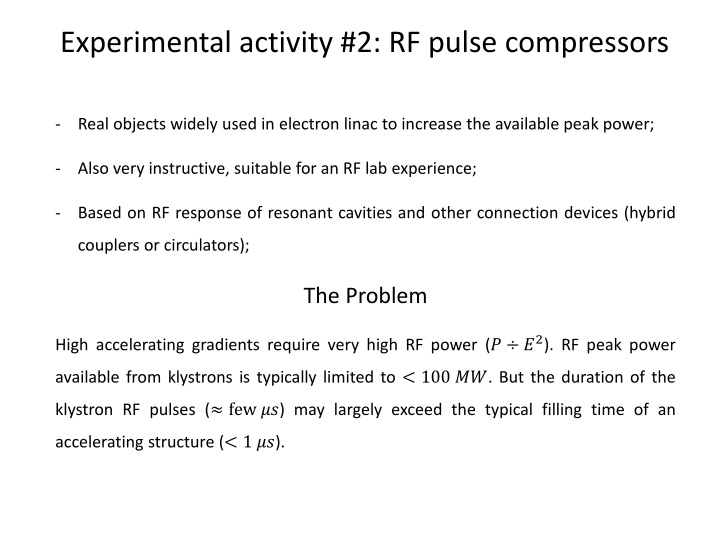
Experimental activity #2: RF pulse compressors - Real objects widely used in electron linac to increase the available peak power; - Also very instructive, suitable for an RF lab experience; - Based on RF response of resonant cavities and other connection devices (hybrid couplers or circulators); The Problem High accelerating gradients require very high RF power (? ?2). RF peak power available from klystrons is typically limited to < 100 ??. But the duration of the klystron RF pulses ( few ??) may largely exceed the typical filling time of an accelerating structure (< 1 ??).
The Idea: SLED (Stanford Linac Energy Doubler) Let s compress the energy of the RF pulse in about 1 filling time to increase the peak power to the maximum! 200 ?? 50 ?? Pulse Compression 4 ?? ???????? ?? ????? ????? ?????? 200 ? 1 ?? A factor of 4 in power corresponds to a factor of 2 in accelerating gradient, i.e. In beam energy. Smart idea! But how a large RF power flowing in a waveguide can be manipulated in order to be compressed? This idea has been firstly implemented at SLAC in the 70 s [1]. The compression is obtained by capturing the RF power reflected by high-Q resonant cavities. [1] Farkas et al. - SLED A method of doubling SLAC energy
Coupling coefficients of a resonant cavity Real resonant cavities are NOT perfectly closed volumes, i.e. at least 1 opening (port) must be present to allow the RF power to flow in (and out). The coupling strength of a port can be measured as the amount of power ???? extracted from the cavity through the port itself for a given level of the mode fields inside. This leads to the definitions of the external-Q (????) (in analogy with the definition of the resonance quality factor ?0) and coupling coefficient of a coupler according to : Q P U = = = 0 out ; Q ext P Q walls P out ext where ?0 is the usual quality factor of the resonant mode, related only to the dissipation on the cavity walls. The extra-power flow through the cavity couplers, in addition to the power loss in the walls, may significantly change the characteristics of the resonance. This effect is known as cavityloading . The loaded cavity Q-factor is lowered by the power coupled out through the cavity ports and results to be: 1 1 1 = + Q Q Q P 0 L ext P 1 U U n out = = = + walls Q n L + P P P Q U U Q + 1 Tot walls out L 1 n n = Q 0 L
Wave reflection in guide terminated on a resonant load A resonant cavity is a non-matched load for a waveguide or a transmission line, and can be modeled as an RLC parallel circuit. ? (?0?0) 2+ ? (?0?0) + 1 ????? = ? ?0 ? ?0 ? = input coupling coefficient 1 ??, ?02= ?0= ?0??0? An RF wave travelling from the generator toward the cavity is always partially reflected at the cavity input. The reflected wave can be calculated according to: ???? ?0 ????+ ?0 ????= ????
Cavity reflected waves and input coupling coefficient In the previous equation, if we substitute the expression for ????, the reflected wave becomes function of the coupling coefficient: Lorentzian network transfer function ???? ?0 ????+ ?0 2? ? ?0?? 2+ ????= ???? = ???? ? ?0??+ 1 1 ? + 1 ? ?0 Depending on the value of the input coupling coefficient ?, 3 practical situations can occur: ? < 1 undercoupling ? = 1 critical coupling ? > 1 overcoupling Let s calculate and plot the wave reflected by a cavity excited by a pulsed source.
Lorentzian network response to RF Pulses The response of a Lorentzian network to an RF step pulse is: ???(?) = ?? ?(? ??????) ??? ??(? ??????) ????? = ?? ? ? ?????? ??? ??(? ??????) ? ? (? ??????) ?; with? = ????? ?????? ??= 25000;?0= 2856 ???;??????= 0.5 ??; ? 2.8??
Lorentzian network response to RF Pulses The response of a Lorentzian network to an RF rectangular pulse is: ???(?) = ?? ??? ??(? ??????) ? ? ?????? + ?(? ????) ? ? ?????? ? ? ? ? ???? ? ? ( ? ?????? ?+ ????? = ?? ??? ??(? ??????) with? = ????? ? ????) ? ?????? ???? ??= 25000;?0= 2856 ???;??????= 0.5 ??;????= 5.5 ??; ? 2.8??
RF step pulse reflected by a resonant cavity The reflected power of a Lorentzian network to an RF step pulse has the following transfer function: 2? ? ?0?? 2+ ????= ???? ? ?0??+ 1 1 ? + 1 ? ?0 In time domain: 2? 1 ? ? ? 1 ????(?) = ?0 1(?) ??? ?0? ; ????? = ?0 1 ? ??? ?0? ? + 1 Undercoupled, ? < 1 Critically coupled, ? = 1 Overcoupled, ? > 1
RF rectangular pulse reflected by an over-coupled resonant cavity The wave reflected by an over-coupled cavity excited by a rectangular RF pulse is: ????(?) = ?0 ??? ?0? 1 ? 1(? ??) 2? 2? 1 ? 1 ? ? ?? ? 1 ? ? 1 1 ? ?? ????? = ?0 ??? ?0? 1 ? ? + 1 ? + 1 ?? The RFL peak field is maximum at the end of the FWD pulse, and its value exceeds the peak of the FWD itself. This effect can be enhanced by forcing a 180 phase jump in the driving pulse at a certain time before the end of the pulse. By doing that we induce an equivalent step in the driving signal of double amplitude which adds in phase with the signal originated by the first rising front of the driving RF pulse. ????(?) = ?0 ??? ?0? 1 ? 2 1 ? ?? + 1(? ??) ?? 2? 2? 2? 1 ? 1 ? ? ?? ? 1 ? ? 1 2 1 ? ?? 1 ? ? ?? ? 1 + 1 ? ?? ????? = ?0 ??? ?0? 1 ? ? + 1 ? + 1 ? + 1
All this power has to be delivered to the accelerator and not to the power units (e.g. klystrons) Circulators are non-reciprocal (typically) 3-ports devices whose scattering matrix is ideally given by: 90 hybrids are non-reciprocal (typically) 4-ports devices whose scattering matrix is ideally given by: 0 0 1 0 0 1 j = 1 0 0 S 0 0 1 j 1 0 1 0 = S 2 1 0 0 j 1 0 0 j
Experimental activity #2 Frequency domain: tuning demonstration Time domain: set-up of the RF pulse CW signal at 2856 MHz Pulsed signal at 2856 MHz (5 us length, 100 Hz rep. rate) Time domain: visualization of SLED output pulse w/o 180 phase jump Resonant frequency fine tuning Frequency domain: realization of the 180 phase jump Design of a 180 phase shifting circuit Functionality cross-check of the 180 phase shifter provided Actual phase shift measurement Timing of the trigger signals Time domain: visualization of SLED output pulse with 180 phase jump Eventual optimization of the SLED pulse Qualitative measurement of energy/power gain Scan Tjump vs energy gain 90 hybrid Output port Input port High Q cavities

")