Sewage: Definition, Flow, and Equations
Sewage is a combination of liquid wastes from various sources, including residences, businesses, and industrial establishments. Learn about the characteristics of sewage, its flow in sewers, and equations used to calculate flow parameters in open channels and partially filled pipes.

Download Presentation

Please find below an Image/Link to download the presentation.
The content on the website is provided AS IS for your information and personal use only. It may not be sold, licensed, or shared on other websites without obtaining consent from the author.If you encounter any issues during the download, it is possible that the publisher has removed the file from their server.
You are allowed to download the files provided on this website for personal or commercial use, subject to the condition that they are used lawfully. All files are the property of their respective owners.
The content on the website is provided AS IS for your information and personal use only. It may not be sold, licensed, or shared on other websites without obtaining consent from the author.
E N D
Presentation Transcript
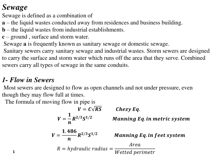
Sewage Sewage is defined as a combination of a the liquid wastes conducted away from residences and business building. b the liquid wastes from industrial establishments. c ground , surface and storm water. Sewage a is frequently known as sanitary sewage or domestic sewage. Sanitary sewers carry sanitary sewage and industrial wastes. Storm sewers are designed to carry the surface and storm water which runs off the area that they serve. Combined sewers carry all types of sewage in the same conduits. 1- Flow in Sewers Most sewers are designed to flow as open channels and not under pressure, even though they may flow full at times. The formula of moving flow in pipe is ? = ? ?? ? =? ???/???/? ????? ??. ??????? ??.?? ?????? ?????? ? =?.??? ??/???/? ??????? ??.?? ???? ?????? ? ???? ? = ???????? ?????? = ?????? ???????? 1
? ?? ?? ????? ?? ???????? ????? ???? ?? ?? ???? ??????,?? ????? ?? ????? ?????????? ??????? ????. ? an? ? are coefficients such that ??.? + ?.????/? + ?.??/? ? + (??.? +?.???? ? = )(? ?) ? For concrete n = 0.015 Experience indicates that a velocity of not less than 0.6 m/s (2 ft/s ) is required in sanitary sewers in order to prevent settlement of the sewage solids. In storm sewers greater velocities will be required than in sanitary sewers because of the heavy sand and grit which will be washed into them. The minimum allowable velocity 0.76 m/s (2.5 ft/s ). The upper limit of high velocities is 2.439 m/s (8 ft/s). 2
2- EQUATIONS FOR FLOW OPEN CHANNELS AND PARTIALLY FILLED PIPES ? =? ???/???/? ? = ?.? =? ?? ??/???/? K= 1 for SI-system K = 1.489 for ft-system ? =?? ?(? ???? ) ? =? ?(? ?) = ? r ? =? ?=? ? = ? ???(? ? (? ???? So , for a given So , for a given Q Qo o , the depth y is , the depth y is ? ) ? =? ?? ??/???/? ? ) ? ? ?/? ??/? ?? ?(? ???? ) ? = ? ? ??? ??=? ? ? (? ???? ? ) ? ? = ? ??? ?(? ? 3 ?)
The following table summarizes the equations used to calculate the primary parameters of interest for the flow in open channels and partially filled pipes. The subsequent sections cover each of the components used in the equations below. 4
It is frequently necessary to determine the velocity and depth of sewage in a pipe which is flowing only partially full. Use the following figure. ? ?= ?.??? ?? ? =5 5. .2766 ? ?= ?.?? ?? ? = ?.???? ??? note that: Qmax at Vmax at 2766 rad rad 5
Example 1: Find the depth of flow and velocity of 36 in. circular sewer is laid on a slope of 0.003 , n = 0.013 when the sewer carrying 5 ???/? . ? =1.486 ?2/3?1/2 ? ? For full flow, y= 2r = d = 36/12= 3 ft ? ? ? ?? = ? ? ???=? ? ? =? ? ? ? = ? = ? , ? = ? ? = ?? , = ? = 2 3 ? 9 4 ? 1 2= 36.53??3 1.486 0.013 3 4 ? ????? ???? , ?? = 0.003 ? 2 3 ?? =1.486 ?2/3?1/2=1.486 3 4 1 2= 5.17 ??/? ? ????? ????????, 0.003 ? 0.013 ?????. ????? 5 ? = 36.53= 0.14 ? = 0.26 36 = 9.4 ??. ???? ? ??? = 0.26 ????? To obtain the velocity find where the horizontal line through 0.26 intersects the velocity curve and read the ratio in the horizontal scale , which is 0.68 . ? = 0.68 ? = 0.68 ?????= 0.68 5.17 = 3.52 ??/? ????? 6
3- Design of Sewer Systems The steps in the design of a sewer system are as follows: 1- Preliminary investigation 2- The detailed survey 3- The actual design 4- Preparation of final map, plans, profiles and specifications which are to guide construction work. 5- Correction of plans to conform to changes made during construction. When the design is completed, the sewer lines are shown as in the following figure: M.H. 17 M.H. 18 M.H. 19 Bore Hole 21 M.H. 20 Bore Hole 20 Bore Hole 22 250 mm 260 mm Bore Hole 23 0.01 0.0076 Rock 250 mm 0.0025 G.L 35.4 I.L 33.2 Dep. 2.2 G.L 32.7 I.L 31.0 Dep. 1.7 G.L 30.4 I.L 27.4 Dep. 3.0 G.L 26.6 I.L 24.1 Dep. 2.5 7
Example 2: A sewer with full flow of 0.28 ?? 100 m. The ground levels at Manhole A is 33 m. and at Manhole B is 32 m. The cover over the pipe is at least 1.8 m at each Manhole. Find the following: 1- the required discharge of depth 0.1 m if n = 0.013 , the velocity of flow in the pipe at least 0.6 m/s and must not exceed 3 m/s. 2- the invert level (I.L.) of the pipes under Manholes A and B. ?enters Manhole A . The distance to Manhole B is ? =? ???/????/? ? ??? , ? = ? ? , ? = 2 3??2 4 ? = 0.45 ? ?.? ?.??= ?.?? ? = 0.09 0.28 = 0.025 ?3/? ?.?? ? ?.??? ? = 1.76 0.6 = 1.06? Solution ? ??? ?? = ? ? ? = For full flow, y= 2r = d, ? = ? 1 ? 4 0.010.5 0.28 = 0.013 ? ?? ? ?? = = ?.?? ? ?? = ?.? ; ??= = ?.?? ?/? ? ? ?.?. I.L. of the pipe under Manhole A = 33 1.8 0.45 =30.75 m I.L. of the pipe under Manhole B = 30 75 - 0.01 100 = 29.75 m 8
Example 3: A sewer system is to be designed for the urban area of the following figure . Street elevations at Manhole locations are shown below. It has been determined that the population density is 40 persons per 4050 ?? and that the sewage contribution per capita per day is 378 liters. There is an infiltration component of 0.56 liter per meter square per day. Local regulations require that no sewers be less than 200 mm in diameter. Assume n = 0.013. M. H No. 1 2 3 4 5 6 7 8 9 Street El. 30.88 31.76 32.11 32.7 33.3 34.2 35.55 34.16 35.07 M. H No. 10 11 12 13 14 15 16 17 18 Street El. 35.8 34.69 33.63 35.3 34.12 33.1 35.48 34.32 33.2 9
7 6 2 9 8 10 3 5 4 12 11 4 13 14 15 3 17 16 18 2 1 To Treatment Plant 10
Increamental area, ??? From Manhole To Pipe No. L, m Manhole 1 7 6 192 0.352 2 6 5 143.3 0.021 3 9 8 118.9 0.05 4 8 5 117.4 - 5 5 4 100.6 0.02 6 10 11 125 0.04 7 11 12 122 0.025 8 12 4 115.9 0.019 9 4 3 112.8 - 10 16 17 115.9 0.02 11 17 18 122 0.02 12 18 3 123.5 0.017 13 13 14 122 0.053 14 14 15 115.9 0.021 15 15 3 125.3 0.039 16 3 2 70.1 - 17 2 1 182.9 - 11 Total Area 0.697
? ? Solution: Flow = ?? ??? ????= ?.??? ?.?? ? ????? ???? = ?.??? + ?.?? = ?.??? ?.?? ?????? ???? = ? ????? ???? ?? ?.?? ? = ? ?.??? = ??.??? ?.??= ?.??? Increament area, ??? Cumulative area, ??? Sewage Flow, ??/? Sewage Flow, ??/? Pipe No. From Manhole To L, m Manhole 1 7 6 192 0.352 - 4576 0.053 2 6 5 143.3 0.021 0.373 4849 0.056 3 9 8 118.9 0.05 - 650 0.008 4 8 5 117.4 - 0.05 650 0.008 5 5 4 100.6 0.02 0.443 5759 0.07 6 10 11 125 0.04 - 520 0.006 7 11 12 122 0.025 0.065 845 0.01 8 12 4 115.9 0.019 0.084 1092 0.013 9 4 3 112.8 - 0.527 6851 0.079 12 10 16 17 115.9 0.02 - 260 0.003
Sewage Flow, ?? /? Increament area, ??? Cumulative area, ??? Sewage Flow, ??/? Pipe No. From Manhole To L, m Manhole 11 17 18 122 0.02 0.04 520 0.006 12 18 3 123.5 0.017 0.057 741 0.009 13 13 14 122 0.053 - 689 0.008 14 14 15 115.9 0.021 0.074 962 0.011 15 15 3 125.3 0.039 0.113 1469 0.017 16 3 2 70.1 - 0.697 9061 0.105 17 2 1 182.9 - 0.697 9061 0.105 Note that : 1- If a sewer changes direction in a manhole without change of size, a drop of 1 cm (or 0.04 ft) is to be provided in a manhole. 2- If the sewer changes size, the crowns of the inlet and outlet sewers are to be at the same elevation. 13
? ?? ? ?? Q Dia. Cal. Dia. Sel. V m/s ????? From To S y ??/? 7 6 0.053 0.007 0.256 0.3 0.081 0.59 0.177 1.08 1.24 6 5 0.056 0.0063 0.266 0.3 0.077 0.62 0.186 1.1 1.2 9 8 0.008 0.0077 0.124 0.2 0.029 0.37 0.074 0.85 0.78 8 5 0.008 0.0073 0.125 0.2 0.028 0.38 0.076 0.85 0.76 5 4 0.07 0.006 0.292 0.3 0.075 0.75 0.225 1.15 1.22 10 11 0.006 0.009 0.108 0.2 0.031 0.3 0.06 0.73 0.72 11 12 0.01 0.0087 0.131 0.2 0.031 0.4 0.08 0.88 0.87 12 4 0.013 0.008 0.147 0.2 0.029 0.46 0.09 0.96 0.89 4 3 0.079 0.0052 0.314 0.35 0.105 0.64 0.224 1.11 1.21 16 17 0.003 0.01 0.082 0.2 0.033 0.22 0.044 0.6 0.63 17 18 0.006 0.0092 0.107 0.2 0.031 0.3 0.06 0.74 0.73 18 3 0.009 0.0088 0.126 0.2 0.031 0.38 0.076 0.85 0.84 13 14 0.008 0.0097 0.119 0.2 0.032 0.34 0.068 0.8 0.81 14 15 0.011 0.0088 0.136 0.2 0.031 0.42 0.084 0.9 0.89 15 3 0.017 0.0079 0.163 0.2 0.029 0.55 0.11 1.4 1.29 3 2 0.105 0.005 0.352 0.4 0.147 0.62 0.248 1.1 1.29 2 1 0.105 0.0048 0.355 0.4 0.144 0.63 0.252 1.11 1.27 14
Example 4: Calculate the invert elevations of all pipes at manholes of above example if the minimum cover is 1.5 m over the sewers. Pipe No. U/S Manhole Level D/S Manhole Level From To L S 1 7 6 192 0.007 33.75 32.41 2 6 5 143.3 0.0063 32.41 31.51 3 9 8 118.9 0.0077 33.37 32.45 4 8 5 117.4 0.0073 32.45 31.59 5 5 4 100.6 0.006 31.5 30.9 6 10 11 125 0.009 34.1 32.98 7 11 12 122 0.0087 32.97 31.91 8 12 4 115.9 0.008 31.91 30.98 9 4 3 112.8 0.0052 30.85 30.26 10 16 17 115.9 0.01 33.78 32.62 11 17 18 122 0.0092 32.62 31.5 12 18 3 123.5 0.0088 31.5 30.41 13 13 14 122 0.0097 33.6 32.42 15
U/S D/S Pipe No. From To L S Manhole Level Manhole Level 14 14 15 115.9 0.0088 32.42 31.4 15 15 3 125.3 0.0079 31.4 30.41 16 3 2 70.1 0.005 30.21 29.86 17 2 1 182.9 0.0048 29.85 28.97 16