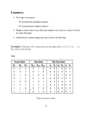
Synchronous Transmitter Medium State Information in IEEE 802.11-20
Explore how devices in synchronous mode handle medium state information during transmission, addressing restrictions on simultaneous TX/RX behavior. The document discusses mechanisms for maintaining medium state across different links and the conveyance of medium state information between devices.

Download Presentation

Please find below an Image/Link to download the presentation.
The content on the website is provided AS IS for your information and personal use only. It may not be sold, licensed, or shared on other websites without obtaining consent from the author. If you encounter any issues during the download, it is possible that the publisher has removed the file from their server.
You are allowed to download the files provided on this website for personal or commercial use, subject to the condition that they are used lawfully. All files are the property of their respective owners.
The content on the website is provided AS IS for your information and personal use only. It may not be sold, licensed, or shared on other websites without obtaining consent from the author.
E N D
Presentation Transcript
doc.: IEEE 802.11-20/0082r0 January 2020 Synchronous Transmitter Medium State Information Date: 2020-01-09 Authors: Name Affiliations Address Phone Email Matthew Fischer 250 Innovation Dr, San Jose, CA 95134 Matthew.fischer@broadcom.com Broadcom Submission Slide 1 Matthew Fischer (Broadcom)
doc.: IEEE 802.11-20/0082r0 January 2020 Abstract EHT non-AP STA devices will have operating States with restrictions on TX and RX behavior E.g. Simultaneous TX/RX might be restricted for certain link channel combinations for non-AP STA aka Synchronous mode When a Synchronous STA starts a TX on one Link1, medium state of Link2 is lost Due to NEXT Need a mechanism to maintain Link2 medium state during Link1 TX operation Link1 TX recipient supplies Link2 state information Submission Slide 2 Matthew Fischer (Broadcom)
doc.: IEEE 802.11-20/0082r0 January 2020 Synchronous Transmitter EDCA Problem RED is STA1 TX, other colors are STA1 RX STA1 EDCA Resumes LINK1 RA=STAw, TA=STA1 BA R C LINK2 R R R STA1 EDCA DEAF RA=STAw, TA=STAx Potential Loss of MPDUs at STAx R C BA Potential Loss of MPDUs at STAw STA1 non-AP STA is the first TXOP winner STA1 begins TX on Link1 to STAw STAx attempts transmission to STAw during STA1 Link1 TX STA1 Link1 TX NEXT causes RX failure at STA1 Link2 At end of TX on Link1, STA1 identifies Link2 as IDLE Unless TX on Link2 > -62 at STA1 location Actually, no rule yet on STA1 Link2 CCA sensitivity during Link1 TX! STA1 Link2 Backoff quickly resumes and hits 0, STA1 TX on Link2 to STAw causes existing Link2 PPDU failures E.g. STAw == AP Submission Slide 3 Matthew Fischer (Broadcom)
doc.: IEEE 802.11-20/0082r0 January 2020 Link2 Medium State Information MSI = Medium State Information AP knows that Link1 transmitter STA1 is synchronous mode STA Include bit in PHY header so that AP does not have to look it up AP is asynchronous Could be any asynchronously operating device, e.g. non-AP AP provides medium state information for Link2 to STA1 in the response to STA1 TX to AP AP provides: Duration/End time of concurrent Link2 PPDU Duration/End time of concurrent Link2 NAV Submission Slide 4 Matthew Fischer (Broadcom)
doc.: IEEE 802.11-20/0082r0 January 2020 MSI Conveyance E.g. a new PPDU Built to hold this information E.g. a Null DATA PPDU with A-control field value E.g. within a PHY Header field Not restricted to AP providing information to non-AP STA Any recipient of a PPDU transmitted by a Synch TX mode STA Even if the recipient is also synch mode STA Because that recipient is not performing TX, it has Link2 MSI Submission Slide 5 Matthew Fischer (Broadcom)
doc.: IEEE 802.11-20/0082r0 January 2020 Synchronous Transmitter EDCA Fixed RED is STA1 TX, other colors are STA1 RX LINK1 RA=STAw, TA=STA1 BA+MSI R C RA=STAw, TA=STA1 BA+MSI C LINK2 R L2 EDCA HOLD STA1 EDCA DEAF RA=STAw, TA=STAx R C BA STA1 receives MSI with BA on Link1 STA1 cannot declare Link2 IDLE until it has MSI information STA1 Link2 deafness disappears at end of STA1 TX PPDU STA1 MSI information is determined at end of STA1 RX PPDU BA+MSI STA1 must suspend EDCA until MSI information is available at the end of RX PPDU BA+MSI i.e. L2 EDCA HOLD as shown in the diagram STA1 uses MSI to adjust Link2 Medium State E.g. set CRS, set NAV for Link2 Subsequent operation is per normal EDCA Submission Slide 6 Matthew Fischer (Broadcom)
doc.: IEEE 802.11-20/0082r0 January 2020 MSI Wait Time Because MSI information is in the response frame It is not available when the Link2 deafness first disappears If Link2 is IDLE, then STA1 is performing unnecessary EDCA hold I.e. as long as MSI is not yet available Can include a Link2 IDLE indication in the PHY header When, per the information obtained at the BA transmitter location, Link2 is IDLE at the end time of the Link1 PPDU, the Link2 IDLE indication can be asserted in the PHY Header of BA+MSI This information is available much earlier in the RX PPDU Reduces the wait time for Link2 EDCA resynchronization Submission Slide 7 Matthew Fischer (Broadcom)
doc.: IEEE 802.11-20/0082r0 January 2020 MSI Time in PHY Header Could transform the Link IDLE information into a full wait time I.e. simply put the Link2 BUSY duration in the PHY header of the response frame Value of 0 indicates Link2 IDLE Non-zero value is equivalent of supplying PPDU Length and/or DUR NAV value I.e. equivalent of a PHY header TXOP value for another link I.e. equivalent of PHY header MSI, or a subset of that MSI Submission Slide 8 Matthew Fischer (Broadcom)
doc.: IEEE 802.11-20/0082r0 January 2020 MSI Frame as an MPDU (1) MSI Block MSI Control LINK1 FCS FC DUR RA TA MSI Control Includes a bitmap that indicates the presence and absence of Medium State Information per link A 1 in the bitmap indicates that MSI is present for the link with LinkID corresponding to the position of the bit in the bitmap A 0 indicates that MSI is not present for the corresponding link MSI Block contains N copies of Per Link MSI Where N is equal to the number of bits in the MSI Control bitmap that are equal to 1 The Per Link MSI fields that are present are arranged in ascending order of LinkID Submission Slide 9 Matthew Fischer (Broadcom)
doc.: IEEE 802.11-20/0082r0 January 2020 MSI Frame as an MPDU (2) Per Link MSI May contain three subfields MSI_NAV_INTRA The predicted value of the Intra NAV of the MSI MPDU transmitter for the corresponding link, at the end of the last symbol of the PPDU that carries the MSI MPDU MSI_NAV_BASIC The predicted value of the Basic NAV of the MSI MPDU transmitter for the corresponding link, at the end of the last symbol of the PPDU that carries the MSI MPDU MSI_LEN The predicted value at the transmitter of the MSI MPDU, of a counter that counts down a PHY LENGTH field value following the reception of a valid PHY Header containing PHY LENGTH field information, for the corresponding link i.e. remaining PHY LENGTH value at the MSI transmitter for the specified link at the end of the PPDU carrying the MSI Submission Slide 10 Matthew Fischer (Broadcom)
doc.: IEEE 802.11-20/0082r0 January 2020 MSI Frame as an MPDU (3) Options: The subfields all have an unsigned positive value, with a minimum value of 0 Values may be expressed in microseconds or some larger unit of time The subfields may have positive or negative values, where A positive value indicates the time in the future, starting from the end of the PPDU that contains the MSI, when the indicated medium state variable is expected to change from BUSY to IDLE A negative value indicates the time at which the indicated medium state was expected to have changed from BUSY to IDLE previous to the end of the PPDU Submission Slide 11 Matthew Fischer (Broadcom)
doc.: IEEE 802.11-20/0082r0 January 2020 MSI In the PHY Header The PHY Header may contain bits to indicate MSI IDLE, per link For example, one bit per Link that indicates MSI IDLE or BUSY If this bit indicates BUSY for the link, then the receiving MLD should examine received MPDUs in the same PPDU for more detailed information, e.g. MSI_NAV_BASIC, MSI_NAV_INTRA, MSI_LEN E.g. a 1 indicates IDLE The PHY Header may contain more complete MSI fields, per link E.g. MSI_NAV_BASIC, MSI_NAV_INTRA, MSI_LEN as described in the MSI frame Note: an IDLE State is indicated by all fields having a value of 0 Submission Slide 12 Matthew Fischer (Broadcom)
doc.: IEEE 802.11-20/0082r0 January 2020 MSI Receiver Behavior (1) An MLD that is operating in synchronous mode shall: During transmission on a link, suspend EDCA operation on any other link on which the MLD is unable to assess the medium State according to the performance requirements of receiver minimum sensitivity Suspend EDCA means to act as though the affected link is experiencing a medium BUSY State Submission Slide 13 Matthew Fischer (Broadcom)
doc.: IEEE 802.11-20/0082r0 January 2020 MSI Receiver Behavior (2) MSI Receiver MSI_LEN Counter An MLD that operates in synchronous mode shall Support MSI exchange Implement an MSI_LEN counter for each operating link The MSI_LEN counter for a link shall be set to the value of the received MSI_LEN field for that link and shall count down the appropriate units of time beginning at the end of the last symbol of the received PPDU which contained the MSI_LEN field Submission Slide 14 Matthew Fischer (Broadcom)
doc.: IEEE 802.11-20/0082r0 January 2020 MSI Receiver Behavior (3) A STA that receives MSI for a specific link, shall, for that link: Replace the Intra NAV counter value with the received MSI_NAV_INTRA value after appropriate scaling, if the scaled received value is greater than the Intra NAV value at the time of the end of the last symbol of the PPDU that contained the MSI MPDU Replace the Basic NAV counter value with the received MSI_NAV_BASIC value after appropriate scaling, if the scaled received value is greater than the Basic NAV value at the time of the end of the last symbol of the PPDU that contained the MSI MPDU Submission Slide 15 Matthew Fischer (Broadcom)
doc.: IEEE 802.11-20/0082r0 January 2020 MSI Receiver Behavior (4) Subsequent to a transmission by an MLD on a link that required EDCA to be suspended on another link, the MLD may resume EDCA operation on the links on which it was suspended 1. At the end of a valid PHY signal field of a PPDU received on the link on which it was previously transmitting, when the received PHY signal field contains MSI indication for the suspended link Either full MSI information or an indication that the suspended link is IDLE 2. At the end of the last symbol of a PPDU received on the link on which it was previously transmitting, when the received PPDU contained an MPDU that contained MSI for the suspended link 3. At any time after the end of the transmission, if it receives any valid PPDU PHY Header on the suspended link Submission Slide 16 Matthew Fischer (Broadcom)
doc.: IEEE 802.11-20/0082r0 January 2020 MSI Receiver Behavior (5) If an MSI parameter for a link is received with a negative value in a PPDU, then The recipient of the MSI may perform an adjustment to its backoff process on the affected link E.g. the backoff should be calculated at the end of the receipt of the PPDU containing the MSI, assuming that the magnitude of the negative value of the parameter is effectively that amount of IDLE time that has passed previous to the end of the PPDU For example, if all MSI parameters indicate either 0 or a negative value, then at the end of the receipt of the PPDU, the recipient determines the earliest time, backwards from the end of the PPDU, at which all parameters had reached zero, representing a sum IDLE indication for the link, and the amount of time from that point forward in time to the end of the PPDU is an amount of time considered IDLE for that link which can be used to determine the current state of the EDCA for that link, Submission Slide 17 Matthew Fischer (Broadcom)
doc.: IEEE 802.11-20/0082r0 January 2020 MSI Receiver Behavior (6) Assuming that the EDCA for that link had resumed operation at the time when the link was determined to be IDLE E.g. if the earliest time from the end of the PPDU that was determined to be IDLE according to the values: MSI_INTRA_NAV == -70 MSI_BASIC_NAV == -140 MSI_LEN == -110 Then the earliest IDLE backwards in time from the end of the received PPDU containing the MSI information is 70 usec from the end of the PPDU The recipient can then adjust the backoff process(es) to account for the fact that 70 usec of IDLE medium has elapsed previous to the end of the PPDU reception If the result of the adjustment is that an existing backoff function for the link would have reached 0 before the end of the received PPDU, then the recipient may perform the following steps Submission Slide 18 Matthew Fischer (Broadcom)
doc.: IEEE 802.11-20/0082r0 January 2020 MSI Receiver Behavior (7) Examine the current medium condition Using ED and Preamble detect For a period of one SLOT If the medium is IDLE, then the recipient may initiate a transmission If the medium is BUSY, then the recipient should restart each expired backoff function by choosing a new backoff number either: Randomly OR By using the number that is equal to the number of backoff slots between the calculated IDLE medium start time and the end of the received PPDU This number is potentially different for each backoff function due to potential differences in the value of AIFSN for each backoff function Submission Slide 19 Matthew Fischer (Broadcom)
doc.: IEEE 802.11-20/0082r0 January 2020 MSI Receiver Behavior (8) Subsequent to a transmission by an MLD on a link (e.g. Link1) that required EDCA to be suspended on another link (e.g. Link2), the MLD Shall perform EIFS on Link2 starting from the zero time point of the time value determined from the MSI_LEN value, if the MSI included MSI_LEN information for Link2 Note that the MSI_LEN zero point might be in the past I.e. MSI_LEN might have a negative value Submission Slide 20 Matthew Fischer (Broadcom)
doc.: IEEE 802.11-20/0082r0 January 2020 Synch Transmitter Indication A Synch Transmitter indication should be included in the PHY header of a PPDU So that the recipient of such a PPDU can prepare MSI to be included in the response The indication in the PHY Header could be a single bit that indicates that the PPDU transmitter is operating using synchronous mode Submission Slide 21 Matthew Fischer (Broadcom)
doc.: IEEE 802.11-20/0082r0 January 2020 Straw poll 0 Do you support the inclusion of the following in the SFD: 802.11be shall include a mechanism for the exchange of Medium State Information and rules for the use of that information by a synchronous mode STA YES NO ABS Submission Slide 22 Matthew Fischer (Broadcom)
doc.: IEEE 802.11-20/0082r0 January 2020 Straw poll 1 Do you support the creation of a new frame for conveying other link Medium State Information? YES NO ABS Submission Slide 23 Matthew Fischer (Broadcom)
doc.: IEEE 802.11-20/0082r0 January 2020 Straw poll 2 Do you support the creation of a new A-control subfield for conveying other link Medium State Information? YES NO ABS Submission Slide 24 Matthew Fischer (Broadcom)
doc.: IEEE 802.11-20/0082r0 January 2020 Straw poll 3 Do you support the creation of a link IDLE indication to be added to the PHY header? YES NO ABS Submission Slide 25 Matthew Fischer (Broadcom)
doc.: IEEE 802.11-20/0082r0 January 2020 Straw poll 4 Do you support the insertion of a TXOP-like value in a PHY header to indicate TXOP information for another link? I.e. a link other than the one on which the PPDU appears YES NO ABS Submission Slide 26 Matthew Fischer (Broadcom)
doc.: IEEE 802.11-20/0082r0 January 2020 Straw Poll 5 Do you support that an MLD that operates in synchronous mode shall support MSI information exchange and the rules for reception of MSI? YES NO ABS Submission Slide 27 Matthew Fischer (Broadcom)
doc.: IEEE 802.11-20/0082r0 January 2020 Straw Poll 6 Do you support that an MLD that operates in synchronous mode shall indicate such in a signaling bit within the PHY header of PPDUs that it transmits? YES NO ABS Submission Slide 28 Matthew Fischer (Broadcom)
doc.: IEEE 802.11-20/0082r0 January 2020 Reference [1] Draft P802.11REVmd_D3.0 [2] Draft P802.11ax_D5.0 Submission Slide 29 Matthew Fischer (Broadcom)