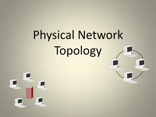
Topology and Metrics in Network Design
Importance of network topology in determining the arrangement of channels and nodes, along with abstract metrics used to evaluate performance and cost. Topics cover degree, hop count, network diameter, and more.

Download Presentation

Please find below an Image/Link to download the presentation.
The content on the website is provided AS IS for your information and personal use only. It may not be sold, licensed, or shared on other websites without obtaining consent from the author. If you encounter any issues during the download, it is possible that the publisher has removed the file from their server.
You are allowed to download the files provided on this website for personal or commercial use, subject to the condition that they are used lawfully. All files are the property of their respective owners.
The content on the website is provided AS IS for your information and personal use only. It may not be sold, licensed, or shared on other websites without obtaining consent from the author.
E N D
Presentation Transcript
ECE 1755 Lecture 17 Interconnects: Topology Winter 2018 Prof. Natalie Enright Jerger Lecture 17 Slide 1 ECE 1755
Topics to be covered Interfaces Topology Routing Flow Control Router Microarchitecture Lecture 17 Slide 2 ECE 1755
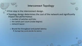
Topology Overview Definition: determines arrangement of channels and nodes in network Analogous to road map Often first step in network design Significant impact on network cost-performance Determines number of hops Latency Network energy consumption Implementation complexity Node degree Ease of layout Lecture 17 Slide 3 ECE 1755
ABSTRACT METRICS Lecture 17 Slide 4 ECE 1755
Abstract Metrics Use metrics to evaluate performance and cost of topology Also influenced by routing/flow control At this stage Assume ideal routing (perfect load balancing) Assume ideal flow control (no idle cycles on any channel) Lecture 17 Slide 5 ECE 1755
Abstract Metrics: Degree Switch Degree: number of links at a node Proxy for estimating cost Higher degree requires more links and port counts at each router B B B 2,3, 4 A 4 2 A A Lecture 17 Slide 6 ECE 1755
Abstract Metrics: Hop Count Path: ordered set of channels between source and destination Hop Count: number of hops a message takes from source to destination Simple, useful proxy for network latency Every node, link incurs some propagation delay even when no contention Minimal hop count: smallest hop count connecting two nodes Lecture 17 Slide 7 7 ECE 1755
Hop Count Network diameter: large min hop count in network Average minimum hop count: average across all src/dst pairs Implementation may incorporate non-minimal paths Increases average hop count Lecture 17 Slide 8 ECE 1755
Hop Count B B B A A A Max = 4 Avg = 2.2 Max = 4 1.77 Max = 2 1.33 Uniform random traffic Ring > Mesh > Torus Derivations later Lecture 17 Slide 9 9 ECE 1755
Latency Time for packet to traverse network Start: head arrives at input port End: tail departs output port Latency = Head latency + serialization latency Serialization latency: time for packet with Length L to cross channel with bandwidth b (L/b) Approximate with hop count Other design choices (routing, flow control) impact latency Unknown at this stage Lecture 17 Slide 10 ECE 1755
Abstract Metrics: Maximum Channel Load Estimate max bandwidth the network can support Max bits per second (bps) that can be injected by every node before it saturates Saturation: network cannot accept any more traffic Determine most congested link For given traffic pattern Will limit overall network bandwidth Estimate load on this channel Lecture 17 Slide 11 ECE 1755
Maximum Channel Load Preliminary Don t know specifics of link yet Define relative to injection load Channel load of 2 Channel is loaded with twice injection bandwidth If each node injects a flit every cycle 2 flits will want to traverse bottleneck channel every cycle If bottleneck channel can only handle 1 flit per cycle Max network bandwidth is link bandwidth A flit can be injected every other cycle Lecture 17 Slide 12 ECE 1755
Maximum Channel Load Example A B E F C D G H Uniform random Every node has equal probability of sending to every node Identify bottleneck channel Half of traffic from every node will cross bottleneck channel 4 x = 2 Network saturates at injection bandwidth Lecture 17 Slide 13 ECE 1755
Bisection Bandwidth Common off-chip metric Proxy for cost Amount of global wiring that will be necessary Less useful for on-chip Global on-chip wiring considered abundant Cuts: partition all the nodes into two disjoint sets Bandwidth of a cut Bisection A cut which divides all nodes into (nearly) half Channel bisection min. channel count over all bisections Bisection bandwidth min. bandwidth over all bisections With uniform traffic of traffic crosses bisection Lecture 17 Slide 14 ECE 1755
Path Diversity Multiple shortest paths between source/destination pair (R) Fault tolerance Better load balancing in network Routing algorithm should be able to exploit path diversity B B B A RA-B = 6 RA-B = 2 RA-B = 1 A A Lecture 17 Slide 16 ECE 1755
Types of Topologies Lecture 17 Slide 17 ECE 1755
Types of Topologies Focus on switched topologies Alternatives: bus and crossbar Bus Connects a set of components to a single shared channel Effective broadcast medium Crossbar Directly connects n inputs to m outputs without intermediate stages Fully connected, single hop network Component of routers Lecture 17 Slide 18 ECE 1755
Types of Topologies Direct Each router is associated with a terminal node All routers are sources and destinations of traffic Indirect Routers are distinct from terminal nodes Terminal nodes can source/sink traffic Intermediate nodes switch traffic between terminal nodes Most on-chip network use direct topologies Lecture 17 Slide 19 ECE 1755
Torus (1) K-ary n-cube: kn network nodes N-Dimensional grid with k nodes in each dimension 2,3,4-ary 3-mesh 3-ary 2-cube 3-ary 2-mesh Lecture 17 Slide 20 ECE 1755
Torus (2) 1D or 2D torus map well to planar substrate for on-chip Topologies in Torus Family Ex: Ring -- k-ary 1-cube Edge Symmetric Good for load balancing Removing wrap-around links for mesh loses edge symmetry More traffic concentrated on center channels Good path diversity Exploit locality for near-neighbor traffic Lecture 17 Slide 21 ECE 1755
Torus (3): Hop Count Average shortest distance over all pairs of nodes Torus: nk 4 k even Hmin= 4-1 nk k odd 4k For uniform random traffic Packet travels k/4 hops in each of n dimensions nk 3 k even Mesh: Hmin= 3-1 nk k odd 3k Lecture 17 Slide 22 ECE 1755
Torus (4) Degree = 2n, 2 channels per dimension All nodes have same degree Total channels = 2nN N is total number of nodes Lecture 17 Slide 23 ECE 1755
Torus Path Diversity 2 dimensions* NW, NE, SW, SE combos 2 edge and node disjoint minimum paths *assume single direction for x and y Lecture 17 Slide 26 ECE 1755
Mesh A torus with end-around connection removed Same node degree Higher demand for central channels Load imbalance Lecture 17 Slide 27 ECE 1755
Butterfly Indirect network 0 1 0 0 0 00 10 20 K-ary n-fly: kn network nodes 1 1 2 2 01 11 21 3 4 3 4 Routing from 000 to 010 Dest address used to directly route packet Bit n used to select output port at stage n 02 12 22 5 5 6 7 6 7 03 13 23 2-ary 3-fly 2 input switch, 3 stages Lecture 17 Slide 28 ECE 1755
Butterfly (2) Rxy=1 No path diversity Can add extra stages for diversity Increase network diameter 0 0 x0 10 20 00 1 2 1 2 x1 11 21 01 3 3 4 4 x2 12 22 02 5 5 6 6 x3 13 23 03 7 7 Lecture 17 Slide 29 ECE 1755
Butterfly (3) Hop Count LogkN + 1 Does not exploit locality Hop count same regardless of location Switch Degree = 2k Requires long wires to implement Lecture 17 Slide 30 ECE 1755
Clos network 3-stage networks where all input/output nodes are connected to all middle routers Key attribute: path diversity Input node can select any middle router Can enable non-blocking routing algorithms (5,3,4) Clos network Lecture 17 Slide 34 ECE 1755
Fat Tree Bandwidth remains constant at each level Regular Tree: Bandwidth decreases closer to root Lecture 17 Slide 35 ECE 1755
Fat Tree (2) Provides path diversity Lecture 17 Slide 36 ECE 1755
Application of Topologies to On-Chip Networks FBFly Convert butterfly to direct network Swizzle switch Circuit-optimized crossbar Rings Simple, low hardware cost Mesh networks Several products/prototypes MECS and bus-based networks Broadcast and multicast capabilities Lecture 17 Slide 37 ECE 1755
Topology Implementation Lecture 17 Slide 38 ECE 1755
Implementation Folding Equalize path lengths Reduces max link length Increases length of other links 0 1 2 3 3 2 1 0 Lecture 17 Slide 39 ECE 1755
Concentration Don t need 1:1 ratio of routers to cores Ex: 4 cores concentrated to 1 router Can save area and power Increases network complexity Concentrator must implement policy for sharing injection bandwidth During bursty communication Can bottleneck Lecture 17 Slide 40 ECE 1755
Implication of Abstract Metrics on Implementation Degree: useful proxy for router complexity Increasing ports requires additional buffer queues, requestors to allocators, ports to crossbar All contribute to critical path delay, area and power Link complexity does not correlate with degree Link complexity depends on link width Fixed number of wires, link complexity for 2-port vs 3-port is same Lecture 17 Slide 41 ECE 1755
Implications (2) Hop Count: useful proxy for overall latency and power Does not always correlate with latency Depends heavily on router pipeline and link propagation Example: Network A with 2 hops, 5 stage pipeline, 4 cycle link traversal vs. Network B with 3 hops, 1 stage pipeline, 1 cycle link traversal latency for B Hop Count says A is better than B But A has 18 cycle latency vs 6 cycle Lecture 17 Slide 42 ECE 1755
Topology Summary First network design decision Critical impact on network latency and throughput Hop count provides first order approximation of message latency Bottleneck channels determine saturation throughput Lecture 17 Slide 43 ECE 1755


")
")
: Hop Count")
")


")
")


")


")