Understanding Generalized Sampling Theorem Interpretation in DSR
Explore the implications of the Generalized Sampling Theorem (GST) in the context of Direct Sparse Reconstruction (DSR) to avoid aliasing in band-limited images. Discover the relationship between inter-sample spacing, transfer functions, and pixel geometries to achieve high-quality reconstructions.

Download Presentation

Please find below an Image/Link to download the presentation.
The content on the website is provided AS IS for your information and personal use only. It may not be sold, licensed, or shared on other websites without obtaining consent from the author. If you encounter any issues during the download, it is possible that the publisher has removed the file from their server.
You are allowed to download the files provided on this website for personal or commercial use, subject to the condition that they are used lawfully. All files are the property of their respective owners.
The content on the website is provided AS IS for your information and personal use only. It may not be sold, licensed, or shared on other websites without obtaining consent from the author.
E N D
Presentation Transcript
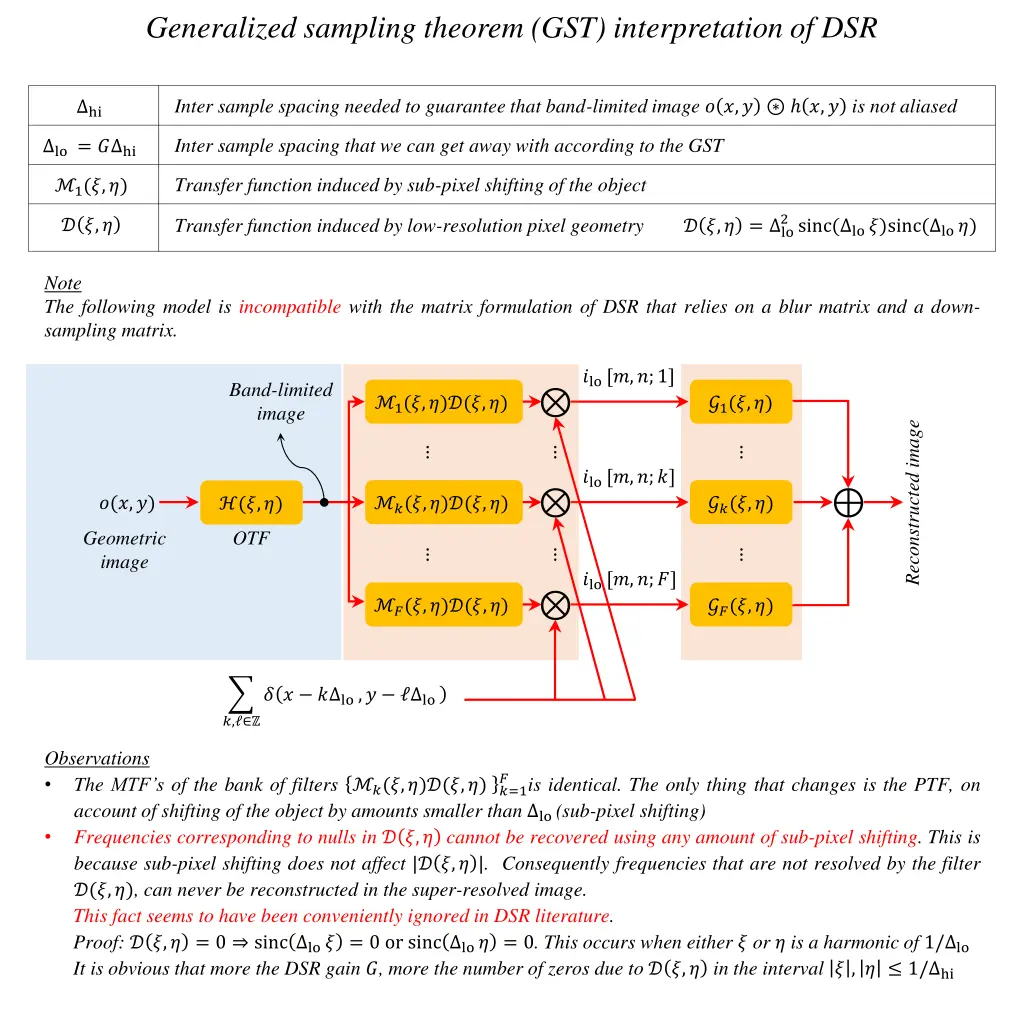
Generalized sampling theorem (GST) interpretation of DSR Inter sample spacing needed to guarantee that band-limited image ? ?,? ?,? is not aliased hi Inter sample spacing that we can get away with according to the GST lo = ? hi Transfer function induced by sub-pixel shifting of the object 1(?,?) 2sinc( lo ?)sinc( lo ?) Transfer function induced by low-resolution pixel geometry? ?,? = lo ? ?,? Note The following model is incompatible with the matrix formulation of DSR that relies on a blur matrix and a down- sampling matrix. ?lo [?,?;1] Band-limited image 1(?,?)?(?,?) ?1(?,?) Reconstructed image ?lo [?,?;?] ?(?,?) ?(?,?)?(?,?) ??(?,?) (?,?) Geometric image OTF ?lo [?,?;?] ?(?,?)?(?,?) ??(?,?) ? ? ? lo ,? lo ?, Observations The MTF s of the bank of filters ?(?,?)?(?,?) ?=1 account of shifting of the object by amounts smaller than lo (sub-pixel shifting) Frequencies corresponding to nulls in ? ?,? cannot be recovered using any amount of sub-pixel shifting. This is because sub-pixel shifting does not affect |? ?,? |. Consequently frequencies that are not resolved by the filter ?(?,?), can never be reconstructed in the super-resolved image. This fact seems to have been conveniently ignored in DSR literature. Proof: ? ?,? = 0 sinc lo ? = 0 or sinc lo ? = 0. This occurs when either ? or ? is a harmonic of 1/ lo It is obvious that more the DSR gain ?, more the number of zeros due to ? ?,? in the interval ? , ? 1/ hi ? is identical. The only thing that changes is the PTF, on
Relationship between geometric image of scene & low-resolution image Inter sample spacing of the detector lo Desired inter sample spacing hi = hi ? Optical Transfer Function ( ????,? ????,? ) ???(?,?) 2sinc lo? sinc lo? 2sinc lo? sinc lo? Transfer function induced by low-resolution pixel geometry NOTE: sinc is an even function lo = lo Assumption The detector geometry of the light sensitive element in the low-resolution imager is assumed to be square, i.e. ????,? = rect lo ? ? rect lo Pixel transfer function of low resolution detector OTF ???(?,?) ?(?,?) ?lo [?,?] 2sinc lo? sinc lo? lo Geometric image of scene Aliased image ? ? ? lo,? ? lo ?,? ?lo [?,?] = ? ?,? ????,? ???? ? lo,? ? lo ????
Equivalent model that is consistent with existing DSR models Inter sample spacing of the detector lo Desired inter sample spacing hi = hi ? Discrete Time Fourier Transform of the sampled optical PSF ?, ???(? hi, hi) (?,?) ? ? hi hi ? lo. ? hi hi ? ?,? Discrete Time Fourier Transform of ? ?, ????,? rect rect ???? ? In the absence of a focal plane mask, ????,? = rect ? ?, has exactly ?2 non-zero entries since ? is an integer. These entries are 1 in the absence of a focal plane mask, and correspond to a ? ? code in the presence of a focal plane mask rect lo Pixel transfer function of high resolution detector Ideal low pass filter ??? Pixel transfer function of low resolution detector 2sinc hi? sinc hi? ? 2?? ?(?,?) hi circ lo hi ?(?,?) ?lo [?,?] (?,?) ? ?,? ?2+ ?2 Geometric image of scene Subsampling Aliased image ?[?, ] ? ? ? hi ,? hi ?, ?lo?,? = ? ?, ? ?? ?,?? = ? ?, ? ?, ? ?, Observations The above model is compatible with the matrix formulation of DSR wherein one is interested in recovering an image of the scene as sampled by a detector with smaller pixels (not just smaller inter-sample spacing) Frequencies corresponding to nulls in either ?,? or ? ?,? cannot be recovered. When not using focal plane masks, the detector integration pattern ?[?, ] corresponds to a linear phase FIR filter with even or odd number of taps. The magnitude response of such a filter can be expressed as a trigonometric series. The problem of nulls in (?,?) ? ?,? may be remedied by diversity in either the sampled PSF or the detector integration geometry (focal plane mask).
Filterbank interpretation of DSR Inter sample spacing of the detector lo Desired inter sample spacing hi = hi ? Discrete Time Fourier Transform of the sampled optical PSF ?, (? hi, hi) (?,?) ? ? hi hi ? lo. ? hi hi ? ?,? Discrete Time Fourier Transform of ? ?, ????,? rect rect ???? ? In the absence of a focal plane mask, ????,? = rect ? ?, has exactly ?2 non-zero entries since ? is an integer. These entries are 1 in the absence of a focal plane mask, and correspond to a ? ? code in the presence of a focal plane mask rect lo ?lo [?,?;1] lo hi lo hi 1(?,?) ?1(?,?) Reconstructed image ?lo [?,?;?] lo hi lo hi ?(?,?) ?(?,?) ??(?,?) Band-limited image ?lo [?,?;?] lo hi lo hi ? ? ? hi ,? hi ?(?,?) ??(?,?) ?, Samples from band-limited image Analysis filter-bank Synthesis filter-bank Observations The above model is compatible with the matrix formulation of DSR
Standard DSR workflow Inter sample spacing of the detector lo Desired inter sample spacing hi = hi ? Discrete Time Fourier Transform of the sampled optical PSF ?, (? hi, hi) (?,?) ? ? hi hi ? lo. ? hi hi ? ?,? Discrete Time Fourier Transform of ? ?, ????,? rect rect ???? ? In the absence of a focal plane mask, ????,? = rect ? ?, has exactly ?2 non-zero entries since ? is an integer. These entries are 1 in the absence of a focal plane mask, and correspond to a ? ? code in the presence of a focal plane mask rect lo lo hi Pixel transfer function of high resolution detector Ideal low pass filter ?lo [?,?;1] 1(?,?) ? ?,? 2sinc hi? sinc hi? ? 2?? ?(?,?) hi circ lo hi ?(?,?) ?lo [?,?;?] ?(?,?) ? ?,? ?2+ ?2 Geometric image of scene lo hi ? ? ? hi ,? hi ?lo [?,?;?] ?(?,?) ? ?,? ?, Image that can be recovered by Digital Super Resolution Analysis filter-bank Observations The above model is compatible with the matrix formulation of DSR wherein one is interested in recovering an image of the scene as sampled by a detector with smaller pixels (not just smaller inter-sample spacing) Any frequencies lost to blurring due to detector integration i.e. ? ?,? = 0 cannot be recovered. This occurs when either ? or ? is a harmonic of 1/ lo . The optical PSF could either be diffraction limited or due to a pseudo-random phase mask as in Amit Ashok s work Sub-pixel shift induces changes in the phase of the transfer function (?,?). These transfer function are denoted as ?(?,?) in the above block schematic.
DSR workflow in Focal Plane Coding Inter sample spacing of the detector lo Desired inter sample spacing hi = hi ? Discrete Time Fourier Transform of the sampled optical PSF ?, (? hi, hi) (?,?) ? ? hi hi ? lo. ? hi hi ? ?,? Discrete Time Fourier Transform of ? ?, ????,? rect rect ???? ? In the absence of a focal plane mask, ????,? = rect ? ?, has exactly ?2 non-zero entries since ? is an integer. These entries are 1 in the absence of a focal plane mask, and correspond to a ? ? code in the presence of a focal plane mask rect lo lo hi Pixel transfer function of high resolution detector Ideal low pass filter ?lo [?,?;1] ?,? ?1?,? 2sinc hi? sinc hi? ? 2?? ?(?,?) hi circ lo hi ?(?,?) ?lo [?,?;?] ?,? ???,? ?2+ ?2 Geometric image of scene lo hi ? ? ? hi ,? hi ?lo [?,?;?] ?,? ???,? ?, Image that can be recovered by Digital Super Resolution Analysis filter-bank Observations The above model is compatible with the matrix formulation of DSR wherein one is interested in recovering an image of the scene as sampled by a detector with smaller pixels (not just smaller inter-sample spacing) Any frequencies lost to blurring due to detector integration i.e. ? ?,? = 0 cannot be recovered. This occurs when either ? or ? is a harmonic of 1/ lo . Each low-resolution image utilizes a different focal plane mask. The transfer function due to these masks is denoted as ??(?,?) in the above block schematic.
Papoulis Generalized sampling theorem (GST) Pre-filtering Post-filtering ?1(?) 1(?) ?1(?) ??(?) ?(?) ?(?) ?(?) ??(?) Band-limited signal Reconstructed signal ??(?) ? = 0, for ? 0.5/?0 ?(?) ??(?) ? ? ???0 ?
Generalized sampling theorem (GST) interpretation of Digital Super Resolution Pre-filtering Post-filtering ?1(?) Band-limited image ??? = 0, for ? 0.5/ hi 1? ?1(?) ??(?) ??(?) ???(?) ???? ?(?) ?(?) ?? ??(?) ??? ? Geometric image Reconstructed image ??(?) ?? ??(?) ? ? ? lo ?
 interpretation of DSR")


")
 interpretation of Digital")