Overview of Particle Accelerators and Isotope Production Methods
Explore various types of particle accelerators such as Direct Voltage Accelerators, Van de Graaff Generators, Tandem Van de Graaff Accelerators, and Linear Accelerators used in generating particles for isotope production, research, and industrial applications. These technologies play a crucial role in advancing scientific understanding and producing isotopes for various purposes.

Overview of Particle Accelerators and Isotope Production Methods
PowerPoint presentation about 'Overview of Particle Accelerators and Isotope Production Methods'. This presentation describes the topic on Explore various types of particle accelerators such as Direct Voltage Accelerators, Van de Graaff Generators, Tandem Van de Graaff Accelerators, and Linear Accelerators used in generating particles for isotope production, research, and industrial applications. These technologies play a crucial role in advancing scientific understanding and producing isotopes for various purposes.. Download this presentation absolutely free.
Presentation Transcript
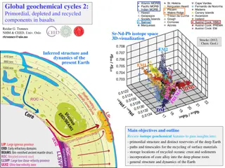
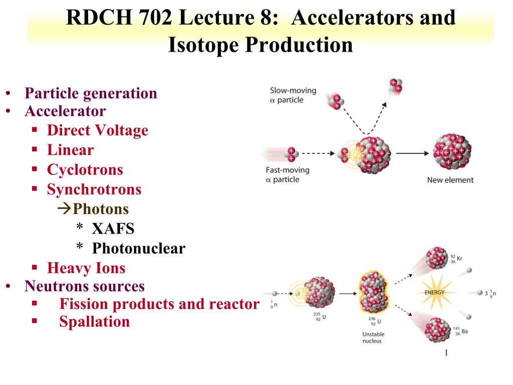
RDCH 702 Lecture 8: Accelerators and Isotope Production Particle generation Accelerator Direct Voltage Linear Cyclotrons Synchrotrons Photons * XAFS * Photonuclear Heavy Ions Neutrons sources Fission products and reactor Spallation 1
Charged Particle Accelerators: Direct Voltage Use of electric fields to accelerate particles First used in 1932 for protons Cascade Rectifiers and Transformers Direct application of voltage between terminals Maximum voltage defined energy limit Use multiple stages of voltage doubling circuits Still used as injectors for high energy accelerator and neutron sources Commercially produced 2
Van de Graaff Generator Electrostatic Generator All potential provide at one source Higher potential than direct voltage First built in 1929, positive charges collected on a belt and used to charge a sphere equilibrium between build up and loss dictates charge on sphere Ion source or electron gun produces ions or electrons which are focused into accelerating tube Accelerating tube under vacuum sections of metal define path focused at ends of metal Well focused beams can be produced Magnetic analyzer may be needed to purify beam H+, H2+, H3+ all accelerated 3
Tandem Van de Graaff Accelerator Negative ions (H-) are accelerated towards positive terminal Inside terminal ions are stripped of electrons Positive ions further accelerated towards ground Can couple more stages Proton energies 25-45 MeV Can also accelerate heavy ions 4
Linear Accelerator Repeated accelerations through small potentials Can use other accelerator output as source Connection of coaxial sections Alternating voltage Ions accelerated at gap First made in 1928 Range of cavities Constant or varied in size Traveling wave Standing wave Electron accelerators on similar principle Pulsed machines Up to 20 GeV Positron acceleration possible (at lower energies) Used for electron scattering, photonuclear reactions, radiation therapy, industrial processing SLAC around 2 miles 5
Proton Linacs Protons and other positive ions have large velocity increase with energy Standing wave acceleration Drift tubes need to increase in length Acceleration at gap between tubes Large energies (up to 800 MeV at LANSCE) Use protons as production tool Mesons Neutrons Spallation products 6
HILACS Heavy ion linear accelerator at LBL Construction similar to tandem Van de Graaffs Accelerate all types of heavy ions, up to U Energies in range of 10 MeV/amu Used in relativistic experiments nuclear structure high energy nuclear collisions injectors 7
Cyclotrons First built in 1930 Multiple acceleration by potential Ions travel in spiral Alternation of dee potential accelerates particles Obeys equations of motion mass m charge q velocity V magnetic field B radius R angular velocity Can control energy by varying terms R often fixed, B can be varied 8
Cyclotrons Fixed Frequency accelerates chosen e/M ratio different energies since M dependent Sector focused useful for heavier ions creates hill and valley in regions Cyclotrons can be combined with Linacs for high energy eV 9
Photon Sources Continuous spectra of EM radiation is emitted when relativistic electrons are in a curved path in a magnetic field Relativistic velocity changes observed frequency due to Doppler effect * Lorentz factor (g) g) Time contraction also increase frequency by g g Forward directed radiation can choose wavelength of photons useful for determining structure IP, PES, EXAFS, XANES Solid state physics Reaction mechanisms Perform many experiments simultaneously 1 dt g = = d 2 1 10
XAS Setup 11
XANES and EXAFS X-Ray Absorption Near Edge Spectroscopy (XANES) Region between absorption edge and start of EXAFS oscillations, up to 40 eV above edge Absolute position of edge contains information on oxidation state Also contains information on vacant orbitals, electronic configuration, and site symmetry Extended X-ray Absorption Fine Structure (EXAFS) Above absorption edge, photoelectrons created by absorption of x-ray Backscattering photoelectrons effect x- ray absorption Oscillations in absorption above edge Oscillations used to determine atomic number, distance, and coordination number of nearest neighbors 12
Bacteria EXAFS EXAFS and Fourier transforms. Slight structural differences can be seen. 13
EXAFS Analysis Structure is consistent with uranyl phosphate Monodentate and bidentate P at 3.61 and 3.04 14
EXAFS Analysis 22 mM Sample Mixture of phosphate and acetate structures Due to high U concentration, phosphate possibly saturated 15
Neutron Sources Radioactive sources (252Cf, reactions) Accelerators 2H(d,n)3H 3H(d,n)4He Neutron energy fast also (g g,n) with 2H or 9Be Alpha-neutron sources Pu-Be sources Reactors specific design high amount of 235U 16
Fission Process Usually asymmetric mass split MH/ML 1.4 for uranium and plutonium due to shell effects, magic numbers Heavy fragment peak near A=132, Z=50, N=82 Symmetric fission is suppressed by at least two orders of magnitude relative to asymmetric fission Occurs in nuclear reactions Competes with evaporation of nucleons in region of high atomic numbers Location of heavy peak in fission remains constant for 233,235U and 239Pu position of light peak increases 2 peak areas for U and Pu thermal neutron induced fission Influence of neutron energy observed 235U fission yield 17
Fission Process Fission yield distribution varies with fissile isotope Heavier isotopes begin to demonstrate symmetric fission Both fission products at Z=50 for Fm As mass of fissioning system increases Location of heavy peak in fission remains constant position of light peak increases 18
Fission products Primary fission products always on neutron-excess side of stability high-Z elements that undergo fission have much larger neutron- proton ratios than stable nuclides in fission product region primary product decays by series of successive - processes to its stable isobar Yields can be determined Independent yield: specific for a nuclide Cumulative yield: yield of an isobar Beta decay to valley of stability Data for independent and cumulative yields can be found or calculated Comparison of cumulative and independent yields for A=141 http://www-nds.iaea.org/sgnucdat/c2.htm 19
Fission Process Nucleus absorbs energy Excites and deforms Configuration transition state or saddle point Nuclear Coulomb energy decreases during deformation Nuclear surface energy increases Saddle point key condition rate of change of Coulomb energy is equal to rate of change of nuclear surface energy Induces instability that drives break up of nucleus If nucleus deforms beyond this point it is committed to fission Neck between fragments disappears Nucleus divides into two fragments at scission point. two highly charged, deformed fragments in contact Large Coulomb repulsion accelerates fragments to 90% final kinetic energy within 10-20 s 20
Proton induced fission Energetics impact fragment distribution excitation energy of fissioning system increases Influence of ground state shell structure of fragments would decrease Fission mass distributions shows increase in symmetric fission 21
Review Notes Describe accelerators Linear Cyclotrons Synchrotrons XANES and EXAFS Describe utilization of photons from synchrotrons Provide example of neutron sources Comment in blog Respond to PDF quiz 22


![[PDF⚡READ❤ONLINE] Cosmology and Particle Astrophysics (Wiley-Praxis Series in As](/thumb/21627/pdf-read-online-cosmology-and-particle-astrophysics-wiley-praxis-series-in-as.jpg)