Digital Systems Lecture 12: Programmable Logics & VHDL Recap
This content provides a comprehensive overview of programmable logic chips, highlighting the benefits of using programmable chips over hard-wired chips and comparing ASICs with programmable chips. It delves into the characteristics of PLAs, CPLDs, and FPGAs, emphasizing the unique features and advantages of FPGAs in offering a sea of possibilities for implementing complex digital systems. The content discusses the flexibility, reconfigurability, and speed of programming FPGAs, making them an attractive choice for various applications.

Download Presentation

Please find below an Image/Link to download the presentation.
The content on the website is provided AS IS for your information and personal use only. It may not be sold, licensed, or shared on other websites without obtaining consent from the author.If you encounter any issues during the download, it is possible that the publisher has removed the file from their server.
You are allowed to download the files provided on this website for personal or commercial use, subject to the condition that they are used lawfully. All files are the property of their respective owners.
The content on the website is provided AS IS for your information and personal use only. It may not be sold, licensed, or shared on other websites without obtaining consent from the author.
E N D
Presentation Transcript
EEE4084F EEE4084F Digital Systems Digital Systems Lecture 12: Programmable Logics, HDL & VHDL Quick Recap Lecturer: Simon Winberg
Lecture Overview Review of short exercise re digital accelerator Programmable logic & HDL
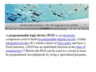
Programmable Logic Chips EEE4084F
Programmable Chips In comparison to hard-wired chips, a programmable chip can be reconfigured according to application or user needs Provides a means to use the same chip(s) for a variety of different applications. Makes programmable chips attractive for use in many products, e.g. prototyping products. Further benefits are: Low starting cost (e.g. Web pack+ FPGA dev kit) Risk reduction Quick turnaround time
ASICs vs. Programmable Chips Application Specific Integrated Circuit (or ASICs) have a longer design cycle and higher engineering cost than using programmable chips. Still a need for ASIC: faster performance and lower cost for high volume Generally, programmable chips are suited to low to medium product production. (e.g. product runs needing under 10,000 chips)
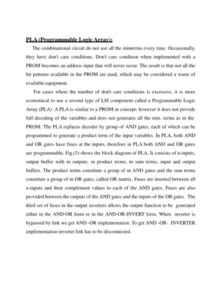
PLAs, CPLDs and FPGAs Programmable logic chips variety in terms simple complex cheap expensive PLA = Programmable Logic Array Simple: just AND and OR gates; but Cheap CPLA = Complex PLA Midrange: compose interconnected PLAs FPGA = Field Programmable Gate Array Complex: programmable logic blocks and programmable interconnects; but Expensive FPGA orders of magnitude larger than CPLD
So what? What is so special about FPGAs? ?
So what? What is so special about FPGAs? FPGA A sea of possibilities 01001010101000100101001010010100 10010010010100100101101001 100100110101011010011101
FPGAs A sea of possibilities The huge number of logic elements (LEs) within these chips, and their many PIO pins, makes it possible to implement large & complex digital systems in them. The ease and speed of programming them provides the ability to rapidly change the hardware (within ms timing) to adapt to application needs. Greater potential for testing and tweaking designs before fabricating them as ICs
Any Drawbacks? Has a limited number of IO pins that can connect up with external signals. Susceptible to EM disturbances, PCB and other components needs to be suitably placed to avoid interfering with functioning of FPGA. Eeek! Only does the digital part still need analogue components, user interface, and circuitry that interacts with the outside world. Typically a slower clock than most fast CPUs nowadays (e.g. 100MHz clock speed). Typically has lots of pins that need to be soldered on, needing small track width and multilayer PCBs A specialized form of development, combines the challenges of both s/w and h/w Often can t achieve full utilization of PLBs Limitations of internal interconnects Place & route can take a long time to complete Things can get rather muddy!
HDL & VHDL Recap EEE4084F
Why use a Hardware Description Language (HDL)? Major reasons for using a HDL: Towards better and more reliable designs Avoid design errors Reduce costs and time General benefits of the HDL approach: Rapidly model and test a functional system/subsystem Means of modeling, testing, refining requirements and specification for a system Formal verification (and an interface to such mechanisms) Testing designs options through use of simulation Synthesis of ICs / digital logic systems
Summary of Elements of the VHDL Paradigm Entity : A part of the system (can be a subsystem) Ports : Connections (or interfaces) between Behavior : What an entity does Structure : What an entity comprises Analysis : Checks syntax, etc. Does various automated tests and simulations on the design to verify that it can be synthesized and deployed on a particular programmable device / IC. Test Bench : How entities or a whole design is tested Synthesis : Deciding gates and how to connect them / generating the bitstream to configure the hardware.
PLD/FPGA Development Flow Design and RTL Coding - Behavioral or Structural Description of Design - Writing VHDL, deciding i/o, formulating tests Design Specification RTL Simulation -Functional Simulation - Verify Logic Model & Data Flow - View model-specified timing M512 LE Synthesis - Translate Design into Device Specific Primitives - Optimization to Meet Required Area & Performance Constraints M4K I/O Place and Route (PAR) - Map primitives to specific locations inside FPGA with reference to area & performance constraints - Specify routing resources to use PTO This development cycle diagram is an adaptation of that prepared by Dr. Junaid Ahmed Zubairi, Avail: http://www.cs.fredonia.edu/zubairi/training/fpga.ppt
Development Flow Place and Route (PAR) Timing Analysis - Verify performance specifications - Static timing analysis tclk Gate Level Simulation -Timing simulation - Verify design will work on target platform Program and test on hardware - Generate bit file - Program target device - Activate the system
Development Flow: Where is most time spent? Every development project is different. In my own experience, most of the time is probably spent Design and RTL Coding - Behavioral or Structural Description of Design - Writing VHDL, deciding i/o, formulating tests Timing Analysis - Verify performance specifications - Static timing analysis tclk Engineer s time Place and Route (PAR) - Map primitives inside FPGA - Specify routing resources to use PC s time
VHDL Basics What VHDL stands for . VHSIC = Very-High-Speed Integrated Circuit VHDL = VHSIC Hardware Description Language VHDL = Very High-level Description Language VHDL = Very Hard Development Language (although you would be kind of right to say VHDL has these properties) * + + *
VHDL Terms and Keywords Entity: designs are expressed in terms of entities, these are components that are interfaced together via ports and maps Architecture: Describes the behaviours of the entity. Each entity can have multiple architectures. Configuration: binds a component instance to a entity-architecture pair Architecture Entity (black box) Configuration Ports Source: Perry, D. 2002. VHDL Programming by Example. 4th ed. McDraw-Hill.
Important Terms Top-level module: module at the top of the hierarchy Package: collection of commonly used data types, subroutines, for implementing architectures Driver: source on a signal Bus: a signal that can have its sources turned off Signal vector: what we usually think of as a bus Attribute: data attached to VHDL objects (e.g., event status) Generic: a parameter to pass information to an entity Process: a basic unit of execution. Multiple processes are usually active at a time. Source: Perry, D. 2002. VHDL Programming by Example. 4th ed. McDraw-Hill.
VHDL Example Let s implement this combinational logic circuit: A C AND2 B 1-bit output 1-bit inputs AND2 operation: C = A AND B
VHDL Example Start by defining the entity: -- Here s a comment library IEEE; use IEEE.STD_LOGIC_1164.ALL; entity AND2 is port ( A : in STD_LOGIC; B : in STD_LOGIC; C : out STD_LOGIC ); end AND2;
VHDL Example Then add an architecture: architecture AND2bhv of AND2 is begin C <= A and B; -- The <= links signals and ports end AND2bhv; Name of this architecture Name of architecture As is the program should compile in Xilinx ISE; the system will create an instance of AND2 as it is the top level module, so no need to add an explicit configuration statement.
Concurrent operation Each statement in a VHDL architecture block executes concurrently, whenever there is a change / event e.g. C <= A and B; -- executes when A or B changes D <= A or B; -- executes when A or B changes If A were to change (e.g. A changes from 0 to 1) then both the lines will execute at once)
Sequential operation Sequential operation is described within a PROCESS block. Example: library ieee; use ieee.std_logic_1164.all; entity fulladder is port (A1, A2, Cin: in std_logic; sum, Cout : out std_logic ); end fulladder; General rule for end: if the structure has a name say end name , if it doesn t use structure_keyword . architecture arch1 of fulladder is begin process(A1,A2,Cin) -- define a sequential operation begin sum <= Cin xor A1 xor A2; Cout <= (A1 and A2) or (Cin and (A1 xor A2)); end process; end arch1; Sensitivity list (note not sensitive to Cout) This line runs first Then this line runs Note: two process blocks in the same architecture block run concurrently A process doesn't have a name so you have to say end process
VHDL coding Best way to learn VHDL is to practice coding with it. General thing to remember to get the syntax right: Outside a PROCESS: COMPONENT declaration SELECT statement WHEN conditional assignment See the VHDL Cheat Sheet on VULA Inside a PROCESS: IF-THEN-ELSE CASE statement But if you haven t done VHDL then note
VHDL coding Note that: we will dive into Verilog next term for Prac4. So if you haven t done VHDL, focus on Verilog. But take note: Computer engineers often end up having to manage with both flavors of HDL to save time by reusing designs. The YODA project can be done in either VHDL, Verilog or a combination of the two. Many large projects end up being a combination of the two just because: engineers might not know the other, or the one HDL might be better suited to solving a problem than the other.
Recommended Steps for VHDL coding 1. Plan dataflow and code entities 2. Implement behaviours 3. Structural modelling (build complex entities using lower level ones) Recommended online VHDL support: http://esd.cs.ucr.edu/labs/tutorial/ This site provides a collection of useful VHDL example code and tutorials
Next lecture The YODA Project Intro to reconfigurable computers Reconfigurable computing case studies Verilog coding