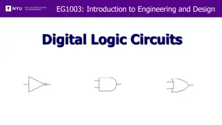
Gates and Logic: Understanding Logic Gates and Circuits

Delve into the fascinating world of logic gates and circuits, exploring the foundational concepts from switches to complex logic functions. Uncover the significance of binary symbols, the role of George Boole in logic gate invention, and the diverse applications of logic gates in modern technology. Explore the basic building blocks, truth tables, and the essential logic gates such as AND, OR, NOT, NAND, NOR, XOR, and XNOR. Discover how these fundamental components form the basis of digital circuits and enable the creation of intricate logic functions.

Download Presentation

Please find below an Image/Link to download the presentation.
The content on the website is provided AS IS for your information and personal use only. It may not be sold, licensed, or shared on other websites without obtaining consent from the author.If you encounter any issues during the download, it is possible that the publisher has removed the file from their server.
You are allowed to download the files provided on this website for personal or commercial use, subject to the condition that they are used lawfully. All files are the property of their respective owners.
The content on the website is provided AS IS for your information and personal use only. It may not be sold, licensed, or shared on other websites without obtaining consent from the author.
E N D
Presentation Transcript
Gates and Logic: Logic Gates and Logic Circuits
Goals for Today From Switches to Logic Gates to Logic Circuits Logic Gates From switches Truth Tables Logic Circuits Identity Laws From Truth Tables to Circuits (Sum of Products) Logic Circuit Minimization Algebraic Manipulations Truth Tables (Karnaugh Maps) Transistors (electronic switch)
A switch Acts as a conductor or insulator Can be used to build amazing things The Bombe used to break the German Enigma machine during World War II
Basic Building Blocks: Switches to Logic Gates Either (OR) + Truth Table A A OFF OFF ON ON B OFF ON OFF ON Light - B Both (AND) + A A OFF OFF ON ON B OFF ON OFF ON Light - B
Basic Building Blocks: Switches to Logic Gates Either (OR) Truth Table A A OFF OFF ON ON B OFF ON OFF ON Light - OR B Both (AND) A A OFF OFF ON ON B OFF ON OFF ON Light - AND B
Basic Building Blocks: Switches to Logic Gates Either (OR) Truth Table A A 0 0 1 1 B 0 1 0 1 Light - 0 = OFF 1 = ON OR B Both (AND) A A 0 0 1 1 B 0 1 0 1 Light - AND B
Basic Building Blocks: Switches to Logic Gates A OR B Did you know? George Boole Inventor of the idea of logic gates. He was born in Lincoln, England and he was the son of a shoemaker in a low class family. A AND B
Takeaway Binary (two symbols: true and false) is the basis of Logic Design
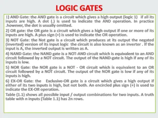
Building Functions: Logic Gates A Out NOT: In A B Out 0 0 0 AND: A 0 1 0 B 1 0 0 1 1 1 OR: A B Out A 0 0 0 B 0 1 1 1 0 1 1 1 1 Logic Gates digital circuit that either allows a signal to pass through it or not. Used to build logic functions There are seven basic logic gates: AND, OR, NOT, NAND (not AND), NOR (not OR), XOR, and XNOR (not XOR) [later]
Building Functions: Logic Gates A Out NOT: In 0 1 1 0 A B Out 0 0 0 AND: A 0 1 0 B 1 0 0 1 1 1 OR: A B Out A 0 0 0 B 0 1 1 1 0 1 1 1 1 Logic Gates digital circuit that either allows a signal to pass through it or not. Used to build logic functions There are seven basic logic gates: AND, OR, NOT, NAND (not AND), NOR (not OR), XOR, and XNOR (not XOR) [later]
Building Functions: Logic Gates A Out NOT: In 0 1 1 0 A B Out A B Out 0 0 0 0 0 1 NAND: AND: A A 0 1 0 0 1 1 B B 1 0 0 1 0 1 1 1 1 1 1 0 NOR: OR: A B Out A B Out A A 0 0 0 0 0 1 B B 0 1 1 0 1 0 1 0 1 1 0 0 1 1 1 1 1 0 Logic Gates digital circuit that either allows a signal to pass through it or not. Used to build logic functions There are seven basic logic gates: AND, OR, NOT, NAND (not AND), NOR (not OR), XOR, and XNOR (not XOR) [later]
Activity#1.A: Logic Gates Fill in the truth table, given the following Logic Circuit made from Logic AND, OR, and NOT gates. What does the logic circuit do? a b Out a b Out
Activity#1: Logic Gates Fill in the truth table, given the following Logic Circuit made from Logic AND, OR, and NOT gates. What does the logic circuit do? a b d Out 0 0 0 0 0 1 0 1 0 a 0 1 1 1 0 0 Out d 1 0 1 1 1 0 b 1 1 1
Goals for Today From Switches to Logic Gates to Logic Circuits Logic Gates From switches Truth Tables Logic Circuits Identity Laws From Truth Tables to Circuits (Sum of Products) Logic Circuit Minimization Algebraic Manipulations Truth Tables (Karnaugh Maps) Transistors (electronic switch)
Logic Gates A Out NOT: 0 1 In 1 0 A B Out 0 0 0 AND: A 0 1 0 B 1 0 0 1 1 1 OR: A B Out A 0 0 0 B 0 1 1 1 0 1 XOR: 1 1 1 A B Out 0 0 0 L ogic Equations Constants: true = 1, false = 0 Variables: a, b, out, Operators (above): AND, OR, NOT, etc. A 0 1 1 B 1 0 1 1 1 0
Logic Gates A Out NOT: 0 1 In 1 0 A B Out A B Out 0 0 0 0 0 1 NAND: AND: A A 0 1 0 0 1 1 B B 1 0 0 1 0 1 1 1 1 1 1 0 NOR: OR: A B Out A B Out A A 0 0 0 0 0 1 B B 0 1 1 0 1 0 1 0 1 1 0 0 XOR: 1 1 1 1 1 0 XNOR: A B Out A B Out 0 0 0 0 0 1 L ogic Equations Constants: true = 1, false = 0 Variables: a, b, out, Operators (above): AND, OR, NOT, etc. A A 0 1 1 0 1 0 B B 1 0 1 1 0 0 1 1 0 1 1 1
Logic Equations NOT: = !a = a out = AND: out = a b = a & b = a b OR: out = a + b = a | b = a b XOR: out = a b = a b + b Logic Equations Constants: true = 1, false = 0 Variables: a, b, out, Operators (above): AND, OR, NOT, etc.
Logic Equations NOT: = !a = a out = AND: NAND: out = a b = !(a & b) = (a b) out = a b = a & b = a b OR: NOR: out = a + b = a | b = a b out = a + b = !(a | b) = (a b) XOR: XNOR: out = a b = ab + ab out = a b = a b + b Logic Equations Constants: true = 1, false = 0 Variables: a, b, out, Operators (above): AND, OR, NOT, etc. .
Logic Manipulation truth tables functions: gates Example: (a+b)(a+c) = a + bc equations a b c 0 0 0 0 0 1 0 1 0 0 1 1 1 0 0 1 0 1 1 1 0 1 1 1