IEEE 802.15-15-0932-00-003e OOK PHY Supporting Material Update
Explore the latest updates on supporting materials for OOK PHY in IEEE 802.15.3e Draft, including channel bonding, spectral mask comparisons, MCS table insights, link budget additions, time direction consistency, and receiver phase/frequency tracking considerations. Get a comprehensive overview of the improvement materials for IEEE P802.15 Working Group for Wireless Personal Area Networks. Stay informed and engaged with the evolving standards in wireless technologies.
Download Presentation

Please find below an Image/Link to download the presentation.
The content on the website is provided AS IS for your information and personal use only. It may not be sold, licensed, or shared on other websites without obtaining consent from the author. If you encounter any issues during the download, it is possible that the publisher has removed the file from their server.
You are allowed to download the files provided on this website for personal or commercial use, subject to the condition that they are used lawfully. All files are the property of their respective owners.
The content on the website is provided AS IS for your information and personal use only. It may not be sold, licensed, or shared on other websites without obtaining consent from the author.
E N D
Presentation Transcript
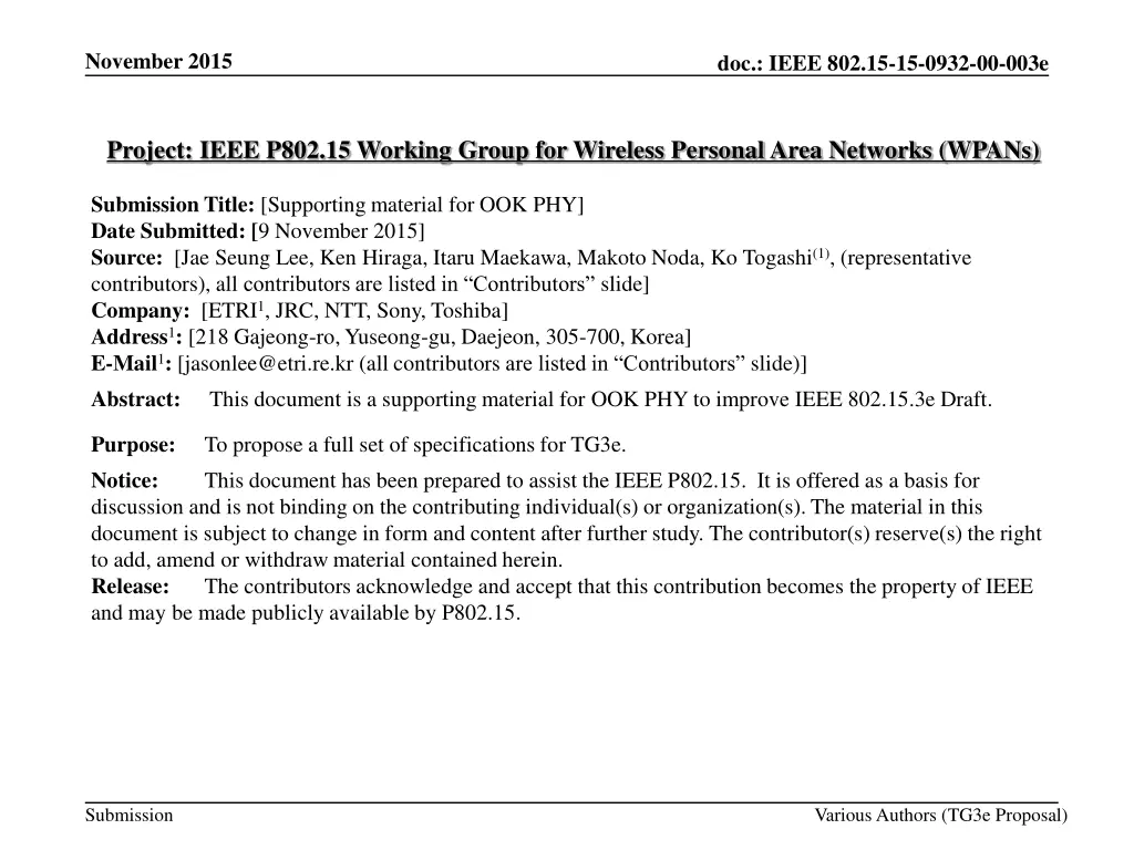
November 2015 doc.: IEEE 802.15-15-0932-00-003e Project: IEEE P802.15 Working Group for Wireless Personal Area Networks (WPANs) Submission Title: [Supporting material for OOK PHY] Date Submitted: [9 November 2015] Source: [Jae Seung Lee, Ken Hiraga, Itaru Maekawa, Makoto Noda, Ko Togashi(1), (representative contributors), all contributors are listed in Contributors slide] Company: [ETRI1, JRC, NTT, Sony, Toshiba] Address1: [218 Gajeong-ro, Yuseong-gu, Daejeon, 305-700, Korea] E-Mail1: [jasonlee@etri.re.kr (all contributors are listed in Contributors slide)] Abstract: This document is a supporting material for OOK PHY to improve IEEE 802.15.3e Draft. Purpose: Notice: discussion and is not binding on the contributing individual(s) or organization(s). The material in this document is subject to change in form and content after further study. The contributor(s) reserve(s) the right to add, amend or withdraw material contained herein. Release: The contributors acknowledge and accept that this contribution becomes the property of IEEE and may be made publicly available by P802.15. To propose a full set of specifications for TG3e. This document has been prepared to assist the IEEE P802.15. It is offered as a basis for Submission Various Authors (TG3e Proposal)
November 2015 doc.: IEEE 802.15-15-0932-00-003e Contributors Name Affiliation Email Jae Seung Lee ETRI jasonlee@etri.re.kr Young-Hoon Kim ETRI yhkim23@etri.re.kr Moon-Sik Lee ETRI moonsiklee@etri.re.kr Itaru Maekawa Japan Radio Co., Ltd maekawa.itaru@jrc.co.jp Lee Doohwan NTT Corporation lee.doohwan@lab.ntt.co.jp Ken Hiraga NTT Corporation hiraga.ken@lab.ntt.co.jp Masashi Shimizu NTT Corporation masashi.shimizu@upr-net.co.jp Keitarou Kondou Sony Corporation Keitarou.Kondou@jp.sony.com Hiroyuki Matsumura Sony Corporation Hiroyuki.Matsumura@jp.sony.com Makoto Noda Sony Corporation MakotoB.Noda at jp.sony.com Masashi Shinagawa Sony Corporation Masashi.Shinagawa@jp.sony.com Ko Togashi Toshiba Corporation ko.togashi@toshiba.co.jp Kiyoshi Toshimitsu Toshiba Corporation kiyoshi.toshimitsu@toshiba.co.jp Submission Slide 2 Various Authors (TG3e Proposal)
November 2015 doc.: IEEE 802.15-15-0932-00-003e Supporting material for IEEE802.15.3e OOK PHY November 12, 2015 Submission Slide 3 Various Authors (TG3e Proposal)
November 2015 doc.: IEEE 802.15-15-0932-00-003e Improvement material OOK 1.Channel bonding vs. aggregation? 1. Draft material, how does the modulated signal achieve the expanded spectrum? (Lee) 2.Need to see the spectrum Technical material was already presented by Noda-san 1. Draft material, spectral mask (Lee) 2. Note: compare with 11ad, ECMA387, bonding, tx pwr, etc. 3.MCS table 1. Supporting material, for example, why do (2,1) and (4,0) have the same throughput but different Tx power? Same situation with (1,1) and (2,0). Need some reason for supporting larger required Eb/No to achieve the same data rate. (Lee) 2. Supporting material, add data rates to the link budget table (Lee) 4.Consistent time direction The draft text has been modified accordingly 1. All diagrams must show increasing time from left to right (Estrada confirm time convention as well as bit ordering convention) 5.What about phase/frequency drift tracking at the receiver? Is 512 too long? 1. Supporting material, how accurate does the Tx signal have to be? (Lee) Submission Slide 4 Various Authors (TG3e Proposal)
November 2015 doc.: IEEE 802.15-15-0932-00-003e Channel Bonding (1/2) HRCP-OOK PHY may use channel bonding using up to four channels for high throughput The channels that are bonded together are adjacent or contiguous to one another Bonded channels are used simultaneously to achieve high throughput The chip rate Rc is increased due to the expanded bandwidth by bonding contiguous channels Parameter Description Value Unit Formula Rc 1760 3520 5280 7040 Chip rate Mchip/s (1 channel) (2 channel) (3 channel) (4 channel) Tc 0.568 0.284 0.189 0.142 1/ Rc Chip duration ns Submission Slide 5 Various Authors (TG3e Proposal)
November 2015 doc.: IEEE 802.15-15-0932-00-003e Channel Bonding (2/2) Transmitted RF signal of OOK ?? ?? 1 ???? ? ??? cos(2????) ???? = ?=0 - ???? transmitted RF signal, ?? : chip duration - ?? ?? : number of transmitted chips in the transmitted OOK PHY frame - ?? : center frequency, ?? : a binary value in the transmitted frame - ??? : baseband pulse shape. It is clear that high throughput can be achieved by the expanded bandwidth Proposed Text: See 12a.3.1 Channel Bonding and 12a.3.2.5.2 Description of Signals in the OOK PHY Draft Slide 6 Submission Various Authors (TG3e Proposal)
November 2015 doc.: IEEE 802.15-15-0932-00-003e Spectral Mask for Channel Bonding Proposed Spectral Mask for Channel Bonding (adopted ITU-R 60 GHz Spectral Mask) Already present by Noda-san Submission Slide 7 Various Authors (TG3e Proposal)
November 2015 doc.: IEEE 802.15-15-0932-00-003e Supporting material on #3 MCS table Submission Slide 8 Various Authors (TG3e Proposal)
November 2015 doc.: IEEE 802.15-15-0932-00-003e Simulation and Performance Evaluation Modulation scheme: OOK with RS(240,224) AWGN and SISO channels are tested. Channel model: Max delay 2.755ns, Same channel model used in [11] Signal Bandwidth: 1.76 GHz~4*1.76 GHz Assumptions and RF models [1] Perfect synchronization No FDE/FDE, Carrier frequency offset (0 ppm) TX & RX Phase Noise for 60GHz K = 87 dBc/Hz, fp = 1 MHz, fz = 100 MHz used in [12] PA nonlinearity G=3.3, p=4.2, Vsat=1.413v, a=8.2x10⁵, b=0.326, q1=10.6, q2=8.0 used in [13] Payload length = 16 Kbytes(=214 bytes) FER @ 8% are adopted as target for required Eb/No Submission Slide 9 Various Authors (TG3e Proposal)
November 2015 doc.: IEEE 802.15-15-0932-00-003e Simulation Result Summary Signal Bandwidth for OOK PHY - 2 Channel bonding with SF=1 and 4 Channel bonding with SF=2 gives the same throughput with the same Tx Power - Single Channel with SF=1 and 2 Channel bonding with SF=2 gives the same throughput with the same Tx Power Submission Slide 10 Byung-Jae Kwak, et al., ETRI
November 2015 doc.: IEEE 802.15-15-0932-00-003e Link Budget Margin (OOK) SISO channel (# of Bonding, SF) Description AWGN (1,1) (2,2) (2,1) (4,2) (3,2) (3,1) (4,1) - 1,630 3,260 2,445 4,890 6,519 Data Rate (Mb/s) Average Tx Power level (Pt) (dBm) -17.55 -17.37 -12.31 -14.85 -5.28 -2.81 Tx_Ant gain (Gt) (dBi) 6 6 6 6 6 6 TX side & Channel Implementation loss (IL) (dB) 6 6 6 6 6 6 Center frequency (fc) (GHz) 60.48 60.48 61.56 60.48 60.48 61.56 Transmission loss at 1m (PL) (dB) 68.1 68.1 68.2 68.1 68.1 68.2 Rx_Ant gain (Gr) (dBi) 6 6 6 6 6 6 Signal Bandwidth (BW) (GHz) 1.76 1.76 3.52 2.64 5.28 7.04 Noise power level (NP) (dBm) -73.3 -73.3 -70.3 -71.6 -68.6 -67.3 RX side System margin (SysM) (dB) 0 0 0 0 0 0 Required Rx level (ReqRx) (dBm) -59.6 -59.4 -54.5 -56.9 -47.4 -45.1 Allowable path loss (APL) (dB) 48.07 48.07 48.21 48.07 48.07 48.26 11.01 (No FDE) 11.19 (No FDE) 13.10 (No FDE) 11.95 (No FDE) 18.51 (FDE) 19.54 (FDE) Required Eb/No (dB) 10 10 10 10 10 10 Maximum transmission range (cm) OBO(Output Back Off) from full saturation: 0 dB, Noise Figure 8 dB Submission Slide 11 Various Authors (TG3e Proposal)
November 2015 doc.: IEEE 802.15-15-0932-00-003e Performance (FER vs. Eb/No) in Channel No FDE FDE FER = 8% Submission Slide 12 Various Authors (TG3e Proposal)
November 2015 doc.: IEEE 802.15-15-0932-00-003e Performance (FER vs. Eb/No) in Channel Throughput = R ( 1- FER) where R is the peak error-free transmission data rate [14] Submission Slide 13 Various Authors (TG3e Proposal)
November 2015 Header Performance (FER vs. Eb/No) in Channel doc.: IEEE 802.15-15-0932-00-003e FER = 8% Submission Slide 14 Various Authors (TG3e Proposal)
November 2015 doc.: IEEE 802.15-15-0932-00-003e Supporting material on #5 Phase/Frequency Tracking Submission Slide 15 Various Authors (TG3e Proposal)
November 2015 doc.: IEEE 802.15-15-0932-00-003e Frequency offset tracking vs. block size (1/2) Maximum frequency offset estimation range Maximum frequency offset is 2.42 MHz with 20 ppm frequency tolerance Maximum frequency offset estimation range is 6.87 MHz Estimated with preamble Enough estimation range No need for non-coherent OOK demodulation Tracking of coherent OOK residual frequency offset for long packet Residual frequency offset is less than initial maximum frequency offset (2.42 MHz) Residual frequency offset tracking with pilot Maximum frequency offset estimation range is dependent for block size. Estimation range for tracking is same as 15.3c OOK PHY. (512 block size 1.72 MHz) No need for further optimization for 15.3e (64 block size 13.75 MHz) 5.5% Data rate loss compared to data rate with 512 block size Submission Slide 16 Various Authors (TG3e Proposal)
November 2015 doc.: IEEE 802.15-15-0932-00-003e Frequency offset tracking vs. block size (2/2) Parameters Value Remarks Carrier Frequency 60.48 GHz Center frequency Frequency tolerance 20 ppm Maximum frequency offset 2.42 MHz 6.87 MHz (72.72 ns) Initial estimation, preamble 1.72 MHz (290.90 ns) Residual frequency offset tracking, pilot with block size 512 Max frequency offset estimation range ( ) 13.75 MHz (36.36 ns) Residual frequency offset tracking, pilot with block size 64 a128 a128 a128 Data Pilot Data Pilot sync T block size Tracking of frequency offset with pilot Initial estimation of frequency offset with preamble Submission Slide 17 Byung-Jae Kwak, et al., ETRI
November 2015 doc.: IEEE 802.15-15-0932-00-003e References [1] TG3e Technical Guidance document, May, 2015 [2] TG3e Channel Modeling document, May, 2015 [3] IEEE 802.15.3 2003 Specification, September 2003 [4] IEEE 802.15.3b 2005 Specification, May 2006 [5] IEEE 802.15.3c 2009 Specification, October 2009 [6] IEEE 802.11 REVmc D4.0, January 2015 [7] 15-14-0639-03-003d, FCC NOI on Frequencies Above 24 GHz, FCC-14-154A1, GN Docket No. 14-177, November 2014 [8] Ken Hiraga et. al, On the Transmission Method for Short-Range MIMO Communication, IEEE TRANSACTIONS ON VEHICULAR TECHNOLOGY, VOL. 60, NO. 3, MARCH 2011 [9] Manabe, T. et. al, Polarization dependence of multipath propagation and high-speed taransmission characteristics of indoor milimeter-wave channel at 60 GHz, IEEE Transactions on Vehicular Technology, 44(2), 268-274 [10] 15-15-0476-00-003e, ETRI Proposal for Close Proximity PHY, July 2015 [11] 15-15-0656-00-003e, Proposal for IEEE802.15.3e-PHY MIMO, September 2015 Submission Slide 18 Various Authors (TG3e Proposal)
November 2015 doc.: IEEE 802.15-15-0932-00-003e References [11] 15-15-0656-00-003e, Proposal for IEEE802.15.3e-PHY MIMO, Sep. 2015 [12] 15-06-0477-01-003c, RF impairment models for 60 GHz band system simulation, 2006 [13] 15-15-0662-01-003e, Proposal for IEEE802.15.3e-Single Carrier PHY, Sep. 2015 [14] X. Zhu and et. al., On the Performance of IEEE 802.15.3c millimeterwave WPANs: PHY and MAC, 2010 6th Conf. on Wireless Advanced, June 2010. Submission Slide 19 Various Authors (TG3e Proposal)
November 2015 doc.: IEEE 802.15-15-0932-00-003e Q & A Submission Slide 20 Various Authors (TG3e Proposal)

