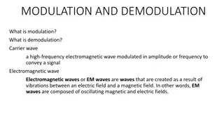
Introduction to Modulation Techniques in Mobile Radio
Modulation is the process of encoding baseband information for transmission, while demodulation extracts the original message. This includes analog and digital modulation methods like Amplitude Modulation (AM). Understanding these techniques is vital for efficient signal transmission in mobile radio systems.

Download Presentation

Please find below an Image/Link to download the presentation.
The content on the website is provided AS IS for your information and personal use only. It may not be sold, licensed, or shared on other websites without obtaining consent from the author. If you encounter any issues during the download, it is possible that the publisher has removed the file from their server.
You are allowed to download the files provided on this website for personal or commercial use, subject to the condition that they are used lawfully. All files are the property of their respective owners.
The content on the website is provided AS IS for your information and personal use only. It may not be sold, licensed, or shared on other websites without obtaining consent from the author.
E N D
Presentation Transcript
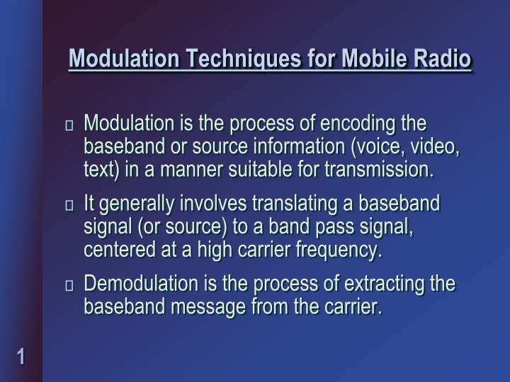
Modulation Techniques for Mobile Radio Modulation is the process of encoding the baseband or source information (voice, video, text) in a manner suitable for transmission. It generally involves translating a baseband signal (or source) to a band pass signal, centered at a high carrier frequency. Demodulation is the process of extracting the baseband message from the carrier. 1
Modulation Techniques Modulation Analog Modulation (First Generation (1G) Mobile Radio) Digital Modulation (2G, 3G, 4G, 5G systems) 2
Review of Analog Modulation Techniques Amplitude Modulation (AM) m(t) Message Signal -- Carrier Signal -- A cos(2 f t) c c AM Signal -- S (t) = A [1+m(t)]cos(2 f t) AM c c 3
Single Singleband AM Signal Lower Sideband = A [m(t)cos(2 f t) m(t)sin(2 f t)] S SSB c c c Upper Sideband Where the Hilbert transform is defined as: m(t) m(t) h(t) = h(t) 1/ t = ; 4
Balanced Modulator Carrier fc 90o S (t) SSB -90o phase shift m(t) 5
Properties of SSB Bandwidth of SSB is very efficient = fm (half of AM bandwidth) However, Doppler spreading and Rayleigh fading can shift the signal spectrum, causing distortion. Frequency of the receiver oscillator must be exactly the same as that of the transmitted carrier fc. If not, this results in a frequency shift fc f, causing distortion. 6
Pilot Tone SSB Transmit a low level pilot tone along with the SSB signal. The pilot tone has information on the frequency and amplitude of the carrier. The pilot tone can be tracked using signal processing FFSR - Feed Forward Signal Regeneration. 7
Properties of TTIB system Base band signal is split into two equal width segments. Small portion of audio spectrum is removed and a low-level pilot tone is inserted in its place. This procedure maintains the low bandwidth of the SSB signal. Provides good adjacent channel protection. 8
Demodulation of AM signals Coherent Modulation Non-coherent demodulation Envelope Detectors 9
Frequency Modulation Message Signal m(t) t FM Signal + 2 A /2 = S (t) A cos[2 f t 2 k m(t)dt] FM C c f = P Power in FM Signal FM c Bandwidth of FM >> Bandwidth of AM (hence higher quality in audio, music) 10
FM methods FM Modulation Direct Method VCO Indirect Method Armstrong FM Detection Slope Detection Zero Crossing Detection PLL Detection Quadrature Detection 11
Comparison between AM and FM FM AM FM signals are less noisy, because amplitude of signal is constant AM signals are more noisy, amplitude cannot be limited The modulation index can be varied to obtain greater SNR(6dB for each doubling in bandwidth) FM signals occupy more bandwidth (good for audio) Modulation index cannot be changed automatically. AM signals occupy lesser bandwidth (good for video) 12
Digital Modulation VLSI and DSP promoted the advent of Digital Modulation Low noise Easier multiplexing of information (voice, data, video) Can accommodate digital transmission errors, source coding, encryption and equalization. DSP can implement digital modulators, demodulators completely in software. 13
Basics of digital communications In digital communication systems, the message) is represented as a time sequence of symbols or pulses. Each symbol has m finite states Number of bits required for m states: n = log2m bits/symbol 14
Shannons bandwidth theorem Shannon's formula: Channel capacity C= Maximum bit rate S/N = Signal to Noise ratio B = Channel bandwidth C = B log2(1 + S/N) 15
Practical digital systems For US digital cellular standard, R = 48.6 kbps RF bandwidth = 30 KHz For SNR 20 dB => 100 C = 30000 * log2(1 + S/N) = 30000 * log2(1 + 100) = 199.75 kbps For GSM standard, R = 270.833 kbps C = 1.99 Mbps for S/N = 30 dB 16
Line Coding Line codes are used to convert bits into voltages. Line codes provide the pulses to represent 0s and 1s. Line codes can be: o Return-to-zero (RZ) o Non-return-to-zero (NRZ) Line codes are Unipolar (0,V) or Bipolar (-V, V ) 17
Unipolar NRZ 1 0 1 1 0 V 0 Unipolar RZ V Bipolar NRZ -V 18
Pulse Shaping Techniques Bandlimited Channel ISI Inter Symbol Interference Due to sharp edges in rectangular pulses Pulse shaping techniques reduce the inter- symbol effects 19
Pulse shaping filters Raised cosine filter cos( t/T ) sin( t/T ) ( t/T ) (1 4 t/2T )s h (t) s = [ ] s RC 2 s As the value of (roll-off factor) increases, the bandwidth of the filter also increases As the value of a (roll-off factor) increases, the time sidelobe levels decrease. 20
Symbol rate with raised-cosine filter Symbol rate possible through raised cosine filter = = + R 1/T 2B/(1 ) s s where B is the filter bandwidth 21
Types of Digital Modulation Linear Non-Linear Spread Spectrum Transmission bandwidth >> signal bandwidth Amplitude of transmitted signal varies linearly with message signal m(t) Amplitude of carrier is constant Low bandwidth- allows more users High bandwidth Low noise More users- high bandwidth Example systems: BPSK, QPSK FSK, GMSK W-CDMA, cdma2000 22
Linear digital modulation PSK or Phase Shift Keying of carrier: SPSK = A cos( t + k) k = 0, (BPSK) k = 0, (QPSK) k = 0, 3 (0PSK) 23
Properties of PSK BPSK BW = 2 RB = 2 / TB Pe,BPSK= Q[ (2 EB / N0)] RB Bit rate, TB Bit period EB /N0 SNR QPSK BW = RB = 1 / TB Pe,QPSK= Q[ (2 EB / N0)] 24
Nonlinear digital modulation Frequency shift keying The frequency of a constant amplitude carrier signal is switched between 2 values ( 1 and 0) = = + c 1/2 S V (t) (2E /T ) cos[2 f 2 f]t,0 T T FSK h b b b = = c 1/2 S V (t) (2E /T ) cos[2 f 2 f]t,0 T T FSK i b b b 25
Properties of FSK Transmission Bandwidth BT = 2 f + 2B B = Bandwidth of digital base-band signal If a raised cosine pulse-shaping filter is used BT = 2 f + (1 + )R Probability of error Pe,FSK = Q[(EB / N0)1/2] 26
Modulation performance in fading channels Fading Channel s(t) r(t) r(t) = (t) e-j (t) s(t) + n(t) (t) = gain of the channel (t) = phase shift of the channel n(t) = additive Gaussian noise 27
BER with noise and fading SNR (with fading) = 2 Eb/No PSK ??= 0.5[1 /(1 + )] FSK ??= 0.5[1 /(2 + )] 28
Spread Spectrum Modulation techniques Spread spectrum techniques employ a transmission bandwidth >> signal bandwidth The system is inefficient for a single user, but is efficient for many users Many users use the same bandwidth without significantly interfering with one another 29
Principle of Spread Spectrum Spread spectrum signals are PN (pseudo noise) sequence or code. Spread spectrum signals are demodulated at the receiver by cross correlation with the correct PN sequence. PN codes are approximately orthogonal, and the receiver can separate each user based on their codes. 30
Advantages of spread spectrum techniques Spread spectrum communications (3G) offer high bandwidth compared to 1G and 2G systems. Resistance to multi-path fading, because of large bandwidths and narrow time widths. 31
PN Sequences Pseudo Noise sequence is a binary sequence of 1s and -1s PN sequences are generated by using sequential logic circuits PN sequence is unique for each user and allows users to share bandwidth without interference 32
Frequency Hopped Spread spectrum (FHSS) A frequency hopping signal periodically changes the carrier frequency by using PN control The set of possible carrier frequencies is called a hopset Hit => Two users using the same frequency band at the same time Bandwidth of channel B Bandwidth of spectrum total bandwidth Wss 33
Methodology of FHSS Time duration between hops hopping period Ts Data is sent by hopping the transmitter carrier over the hopset generated by PN codes Small bursts of data are sent before T/R hops again Hit => Two users using the same frequency band at the same time 34
Frequency Hopping Modulator Frequency Hopping Signal Modulator DATA Frequency Synchronizer Oscillator PN Code Generator Code Block 35
Frequency hopping demodulator Wideband Filter BP Filter Demodulation DATA Frequency Synthesizer Synchronization System Frequency Hopping Signal PN Code Generator 36
Parameters of FH-SS Probability of error for BPSK Spread Spectrum Pe = 0.5 x e -Eb/ 2N0 x (1 ph ) + 0.5 ph ph = probability of hit = 1 (1 1/M)K-1 M = number of hopping channels K = Total number of users Processing gain (PG) = Wss / B 37
Direct Sequence Spread Spectrum (DSSS) code C1 C2 frequency CN time 38
Properties of DSSS signal Message signal is a time sequence of non- overlapping pulses of duration T, each of which has an amplitude (+/-) 1. The PN waveform consists of N pulses or chips for message symbol period T. NTC = T where TC is the chip period. 39
Example: 1 N=4 -1 PN Wave for N =4 1 -1 40
DSSS Transmitter 1 S (t) 1 m (t) r(t) 1 PN (t) + cos(2 f t ) 1 c 1 k mk(t) PN (t) + cos(2 f t ) K 41 c k
CDMA Receiver k iZ (t) (.)dt r(t) m (t) k + cos(2 f t ) PN (t) c k K 42
Parameters of DSSS Probability of bit error (BER) Pe = Q {1/ [(K 1)/3N + (N0/2Eb)]1/2} K = Number of users N = Number of chips/ symbol 43
Important Advantages of CDMA Many users of CDMA use the same frequency Multipath fading may be substantially reduced because of large signal bandwidth. There is no absolute limit on the number of users in CDMA System performance gradually degrades for all users as the number of users is increased. 44
Drawbacks of CDMA Self-jamming is a problem in a CDMA system. Self-jamming occurs because the PN sequences are not exactly orthogonal. The near- far problem occurs at a CDMA receiver if an undesired user has high detected power as compared to the desired user. 45


")


")