Measuring System Latency for Digital Systems
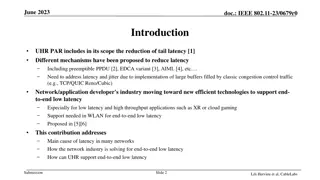
System latency, the delay from sensing to actuation, is crucial in digital systems for efficient performance. This article explores the significance of measuring system latency, its impact on human users and machine systems, and the methods used for measurement. Previous works and the need for continuous measurement are also discussed, emphasizing the importance of constant delay time for optimal functionality.

Download Presentation

Please find below an Image/Link to download the presentation.
The content on the website is provided AS IS for your information and personal use only. It may not be sold, licensed, or shared on other websites without obtaining consent from the author.If you encounter any issues during the download, it is possible that the publisher has removed the file from their server.
You are allowed to download the files provided on this website for personal or commercial use, subject to the condition that they are used lawfully. All files are the property of their respective owners.
The content on the website is provided AS IS for your information and personal use only. It may not be sold, licensed, or shared on other websites without obtaining consent from the author.
E N D
Presentation Transcript
Measuring Digital System Latency from Sensing to Actuation at Continuous 1 ms Resolution Weixin Wu, Yujie Dong, Adam Hoover Dept. Electrical and Computer Engineering, Clemson University
What is system latency Delay from when an event is sensed to when the computer does something (actuates) Examples: camera to display; gyroscope to motor
Why do we care? If delay is constant, human users can adapt, machine systems can be built to specification Constant delay Time
What if it is not constant? May have some relation to simulator sickness ; machines have to be built with a lot more tolerance for variability in delay Varying delay Time
How do we measure it? Components use asynchronous clocks; computer timestamps do not include sensing/actuation times or variability in buffers unmeasured unmeasured Timestamp Timestamp
Indirect system latency measurement Outside observer Measure when the property being sensed/actuated are same Example: marker position in real world matches marker position in display
Previous works (camera based) Actuator Sensor Bryson & Fisher (1990) He, et. al. (2000) Liang, Shaw & Green (1991) Ware and Balakrishan (1994) Steed (2008) Morice et. al. (2008) Outside observer
Previous works (event based) Mine (1993) Akatsuka & Bekey (2006) Olano et.al. (1995) Morice et. al. (2008) Teather et. al. (2009) Outside observer
Why measure continuously? Measure: Time Average infrequent or irregular measurements
Continuous measurement Outside observer is high speed camera Can capture 480 x 640 image resolution at 1,000 Hz for up to 4 seconds
Sensor, object in real world Bar is manually moved right to left in about 1 second
As seen by outside observer Bar position in display lags behind bar position in real world
Automated image processing Calculate P=(X-L)/(R-L) for both events
Continuous latency measurement Plot Ps and Pa for each high speed camera frame
Result frequency magnitude Delay varies with 17 Hz oscillation, 10-20 ms magnitude
Result Histograms, or averages, do not provide the whole picture
Modeling the variability The histogram of delay is uniform but NOT random
As seen by the outside observer Bar on motor lags behind bar being manually rotated
Automated image processing Calculate theta for both events (relative to initial theta)
Result Similar high frequency/magnitude variability as in experiment 1
Result Lines are not parallel lower frequency variability Changes every trial, due to varying sensor error
Fitting sinusoid to low frequency Two examples: Ten trials of 50 degree rotation in 800 ms: 0.5-1.0 Hz variability in delay, magnitude 20-100 ms Seven trials of 10 degree rotation in 800 ms: 0.5-1.0 Hz variability in delay, magnitude 20-100 ms
Conclusion Measuring delay continuously at 1ms resolution shows interesting variations in latency Relation to simulator sickness? Next experiments: control latency variability, test its effect on people


")
")