Understanding Electrotechnology Practices
Learn about the requirements for electrical installation work in Western Australia, including checking, testing, and certification procedures. Find out the essential tests like earth resistance, continuity, insulation, polarity, circuit connections, and RCD operation. Ensure compliance with AS/NZS 3000:2007 standards for safe and effective electrical installations.

Download Presentation

Please find below an Image/Link to download the presentation.
The content on the website is provided AS IS for your information and personal use only. It may not be sold, licensed, or shared on other websites without obtaining consent from the author. If you encounter any issues during the download, it is possible that the publisher has removed the file from their server.
You are allowed to download the files provided on this website for personal or commercial use, subject to the condition that they are used lawfully. All files are the property of their respective owners.
The content on the website is provided AS IS for your information and personal use only. It may not be sold, licensed, or shared on other websites without obtaining consent from the author.
E N D
Presentation Transcript
Electrotechnology Practices By Jeff Hampson Animations by Grahame Byrnes
Preface It is a requirement of the Electricity (Licensing) Regulations 1991 that all electrical installing work carried out in Western Australia complies with the relevant standards, including AS/NZS 3000:2007 and WA Electrical Requirements. All completed electrical work must be checked and tested by a licensed electrician before the work is certified as complying to the relevant network operator. This PowerPoint presentation has been produced as a guide to meeting the checking and testing requirements. While this guide is mainly focused on domestic installations, the principles apply to all electrical installing work. The methods in this presentation are not intended to be exclusive. Other methods may be used, as long as they meet the minimum requirements of AS/NZS 3000:2007
Installation Test Certificate After the installation work is complete, a licensed electrician must carry out checks and tests to make sure that the work meets the requirements of the Wiring Rules. Once the work is confirmed as correct, a Notice of Completion is supplied to the network operator, a Safety Certificate to the client and a Installation Test Certificate is fixed inside the meter enclosure. The electrician is requested to record some key installation test results and the route of the consumer s mains cable on a self adhesive label which is also placed inside the meter enclosure. 1) Main Earth Resistance 2) Earth Continuity or Fault Loop Impedance values of each sub-circuit 3) Insulation resistance value for each sub circuit 3
Installation Test Certificates Preliminary/Completion Safety Certificate 4
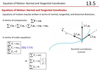
Checking and Testing 1) Visual Inspection - should be carried out whilst referring to a plan to ensure a systematic check to pick up any omissions and to verify that the work complies with the requirements of the applicable standards. 2) Earth Resistance and Continuity Tests - this test includes the main earthing conductor, protective earth conductors and bonding conductors. 3) Insulation Resistance Test - this test is necessary to ensure that the insulation resistance between live parts/conductors and earth is adequate. 4) Polarity Test - used to ensure correct connection of active, neutral and earthing conductors. 5
Checking and Testing 5) Correct Circuit Connections - this test checks earthing conductors do not carry current during normal operation and no short circuit exists. 6) Fault Loop Impedance - measures the fault loop impedance of each circuit to verify the protective device will operate. 7) Verification of RCD (residual current device) Operation - testing of RCDs is carried out to ensure that the RCD operates. 6
9.2 Functional blocks of an electrical installation Point of Supply Load Main Distribution Board Board Final Consumer s Submains Mains Subcircuit
Figure 9.12 Measuring resistance of main earthing conductor Disconnect Equipotential Bonding conductor
Figure 9.13 Resistance test of protective earth at lighting point & fixed equipment (In 3000:2007 Pg 329, Table 8.2) Disconnect Equipotential Bonding conductor
Figure 9.14 Resistance test of protective earth at socket-outlet Disconnect Equipotential Bonding conductor
Figure 9.15 Resistance tests of equipotential bonding conductors Reconnect Equipotential Bonding conductor
Figure 9.16 Resistance test of conduit bonding conductor and conduit continuity
Figure 9.19 Testing the impedance of the earth-fault loop of a final sub-circuit
Figure 9.23a Interconnection tests between conductors of different circuits
Figure 9.23b Interconnection tests between conductors of different circuits
Figure 9.28 Theoretical fall of resistance around an earth electrode x P C 100 Resistance (ohms) 80 60 40 20 0 10m 20m Distance (m)