Understanding Track Reconstruction in Particle Physics
Explore the concepts of track reconstruction, material effects, and field impacts in particle physics, including the definition of a track, infrastructure components, and tracker hits. Learn about the parameters required for determining charged particle paths and the challenges posed by inhomogeneous fields.

Download Presentation

Please find below an Image/Link to download the presentation.
The content on the website is provided AS IS for your information and personal use only. It may not be sold, licensed, or shared on other websites without obtaining consent from the author. If you encounter any issues during the download, it is possible that the publisher has removed the file from their server.
You are allowed to download the files provided on this website for personal or commercial use, subject to the condition that they are used lawfully. All files are the property of their respective owners.
The content on the website is provided AS IS for your information and personal use only. It may not be sold, licensed, or shared on other websites without obtaining consent from the author.
E N D
Presentation Transcript
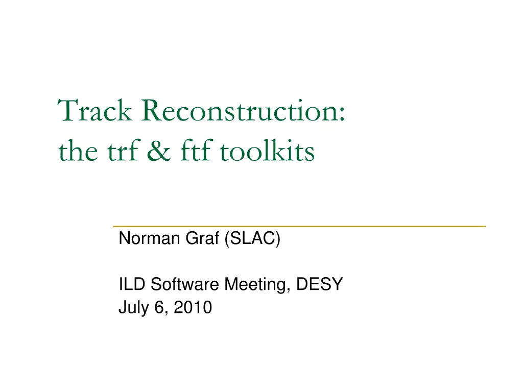
Track Reconstruction: the trf & ftf toolkits Norman Graf (SLAC) ILD Software Meeting, DESY July 6, 2010
What is a track? Ordered association of digits, clusters or hits (finder) Digit = data read from a detector channel Cluster = collection of digits Hit = Cluster (or digit) + calibration + geometry (+track candidate) Provides a measurement suitable to fit a track E.g. a 1D or 2D spatial measurement on a plane Trajectory through space (fitter) Space = 6D track parameter space 3 position + 2 direction + 1 curvature 5 parameters and error matrix at any surface Track is therefore only piecewise helical. default is to break track down by measurement layers. could increase granularity for inhomogeneous fields 2
Track Definition Six parameters are required to determine a charged particle s ideal path in a magnetic field. However, knowing these parameters at a single point (e.g. the distance of closest approach to the beam, dca) is insufficient for precision fits due to material effects (dE/dx, MCS, bremsstrahlung) and field inhomogeneities. No global functional form for the fit. Current LCIO Track interface definition is too simplistic by not allowing for these effects. 3
Material and Field Effects MCS dEdx Brem Knowing Track here does not allow us to know Track state here. 4
Infrastructure components Hit Defined at a surface. Provides a measurement and associated error Provides a mechanism to predict the measurement from a track fit Provides access to underlying cluster and/or digits 5
TrackerHit Current LCIO TrackerHit interface only accommodates three dimensional hits. Many tracking subdetectors only provide one dimensional measurements (silicon microstrips) or two dimensional hits (such as silicon pixels). Furthermore, using Cartesian coordinates is not always the most natural for individual subdetectors. Cylinder: 1D Axial: 1D Stereo: + z 2D Combined: ( , z) XYPlane: 1D Stereo: wv*v + wz*z 2D Combined: (v, z) ZPlane: 1D Stereo: wx*x + wy*y 2D Combined: (x,y) 6
Hits trfcyl: HitCylPhi : a phi measurement on a cylinder. HitCylPhiZ : stereo measurement on a cylinder. phiz = phi + stereo*z. HitCylPhiZ2D : measurement of both phi and z on a cylinder. trfxyp: HitXYPlane1 : one dimensional v-z measurement on a XYPlane. avz = wv*v + wz*z HitXYPlane2 : two dimensional (v,z) measurement on an XYPlane trfzp: HitZPlane1 : one dimensional xy measurement on a ZPlane. axy = wx*x + wy*y HitZPlane2 : two dimensional (x,y) measurement on a ZPlane 7
Surfaces Surfaces generally correspond to geometric shapes representing detector devices. They provide a basis for tracks, and constrain one of the track parameters. The track vector at a surface is expressed in parameters which are natural for that surface. Abstract interface defined, most common surface implementation provided. 8
Cylinder Surface defined coaxial with z, therefore specified by a single parameter r. Track Parameters: ( , z, , tan , q/pT) Bounded surface adds zmin and zmax. Supports 1D and 2D hits: 1D Axial: 1D Stereo: + z 2D Combined: ( , z) 9
XY Plane Surface defined parallel with z, therefore specified by distance u from the z axis and an angle of the normal with respect to x axis. Track Parameters: (v, z, dv/du, dz/du, q/p) Bounded surface adds polygonal boundaries. Supports 1D and 2D hits: 1D Stereo: wv*v + wz*z 2D Combined: (v, z) 10
Z Plane Surface defined perpendicular to z, therefore specified by single parameter z. Track Parameters: (x, y, dx/dz, dy/dz, q/p) Bounded surface adds polygonal boundaries. Supports 1D and 2D hits: 1D Stereo: wx*x + wy*y 2D Combined: (x,y) 11
Distance of Closest Approach DCA is also a 5D Surface in the 6 parameter space of points along a track. It is not a 2D surface in 3D space. Characterized by the track direction and position in the (x,y) plane being normal; = /2. Track Parameters: (r, z, dir, tan , q/pT) 12
Detector Use compact.xml to create a tracking Detector composed of surfaces, along with interacting propagators to handle track vector and covariance matrix propagation, as well as energy loss and multiple scattering. Convert SimTrackerHits in event into: 1-D phi measurements in Central Tracker Barrel 2-D phi-z measurements in Vertex Barrel (pixel) 2-D x-y measurements in forward disks (assume stereo strips) 2-D phi-z measurements in TPC (place hits on cylinders in middle of readout pads) 13
Propagator Propagators propagate a track (and optionally its covariance matrix) to a new surface. A propagator returns an object of type PropStat which describes the status of the attempted propagation: i.e. whether it was successful and, if so, in which direction the track was propagated (forward or backward). Interacting Propagators modify the track and its covariance matrix (in case of energy loss), or just the covariance matrix (thin multiple scattering.) 14
Propagators Propagators are defined for all combinations of surfaces: Cylinder XYPlane ZPlane DCA Provide both simple, but fast, constant-field and full, Runge-Kutta propagators. 15
Interactors Describes the interface for a class which modifies an ETrack. Examples are: Multiple Scattering ThinCylMS ThickCylMS ThinXYPlaneMS ThinZPlaneMS Energy Loss CylELoss 16
Track Finding: ftf Using a conformal mapping technique Maps curved trajectories onto straight lines Simple link-and-tree type of following approach associates hits. Once enough hits are linked, do a simple helix fit circle in r-phi straight line in s-z simple iteration to make commensurate Use these track parameters to predict track into regions with only 1-D measurements & pick up hits. Outside-in, inside-out, cross-detector: completely flexible as long as concept of layer exists. Simple fit serves as input to final Kalman fitter. 17
Summary Improvements are being considered for the LCIO tracker hit and track infrastructure and the ILD track finding and fitting packages. trf toolkit contains a well-tested detector model, track & hit classes and Kalman filter fitting code which accounts for energy loss and MCS. ftf toolkit provides a fast, efficient, pattern recognition package based on a conformal mapping of hits on topological layers. Implementing ftf & trf into the ILD software would require some work. 18