Uplink RSSI Importance for Effective Roaming in IEEE 802.11 Networks
Highlighting the significance of understanding uplink RSSI for making informed roaming decisions in IEEE 802.11 networks. Proposing the inclusion of AP transmit power in Beacon/Probe Response frames to enhance uplink RSSI estimation accuracy, especially in scenarios with varying transmit power levels between devices. Explore motivating scenarios and challenges related to uplink RSSI management for improved Quality-of-Service requirements in modern networking environments.
Download Presentation

Please find below an Image/Link to download the presentation.
The content on the website is provided AS IS for your information and personal use only. It may not be sold, licensed, or shared on other websites without obtaining consent from the author. If you encounter any issues during the download, it is possible that the publisher has removed the file from their server.
You are allowed to download the files provided on this website for personal or commercial use, subject to the condition that they are used lawfully. All files are the property of their respective owners.
The content on the website is provided AS IS for your information and personal use only. It may not be sold, licensed, or shared on other websites without obtaining consent from the author.
E N D
Presentation Transcript
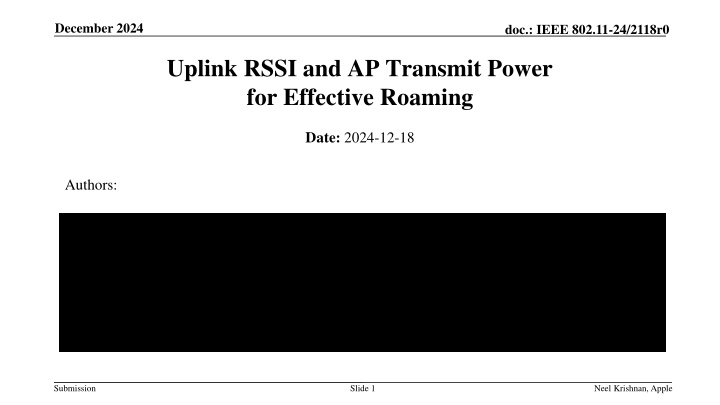
December 2024 doc.: IEEE 802.11-24/2118r0 Uplink RSSI and AP Transmit Power for Effective Roaming Date: 2024-12-18 Authors: Submission Slide 1 Neel Krishnan, Apple
December 2024 doc.: IEEE 802.11-24/2118r0 Abstract Highlight the importance of knowledge of uplink RSSI at a client device to make effective roaming decisions Propose that AP transmit power is included in the Beacon / Probe Response frames to facilitate estimation of uplink RSSI at client Submission Slide 2 Neel Krishnan, Apple
December 2024 doc.: IEEE 802.11-24/2118r0 Motivating Scenarios Importance of Uplink RSSI (1) Advent of new use-cases like augmented reality and virtual reality has imposed stringent Quality-of-Service (QoS) requirements on the uplink (UL) traffic Example: 11-22/779r0 indicates that the target e2e delay for AR/VR applications may be as low as 20 ms UL QoS requirements (throughput, latency) translate to data rate requirements and hence RSSI / SNR target in the uplink Downlink (DL) RSSI may not be a good proxy for the achieved UL RSSI, i.e., high DL RSSI does not necessarily translate to an equivalently high UL RSSI This is especially the case in 6 GHz bands in which transmit power of AP and client devices may be different owing to different regulatory limits; AP max PSD is 6 dB higher than client max PSD Knowledge of the difference in max PSD between AP and client is not sufficient and will lead to inaccurate estimations of uplink RSSI Desirable to devise a scheme that allows a client device to gauge uplink RSSI to roaming candidate AP(s) to make more informed roaming decisions Desirable for the scheme to entail low overhead and provide reasonable accuracy of RSSI Submission Slide 3 Neel Krishnan, Apple
December 2024 doc.: IEEE 802.11-24/2118r0 Motivating Scenarios Importance of Uplink RSSI (2) Refer to the illustration to the above for an example topology It is possible that AP #1 operates at a transmit power lower than AP #2 (e.g., Transmit Power Control (TPC) in enterprise environments) UL RSSI may not follow the same trend as DL RSSI If STA is aware of the uplink RSSI at AP #1 and AP #2, then it can make educated roaming decisions instead of relying exclusively on DL RSSI measurements Submission Slide 4 Neel Krishnan, Apple
December 2024 doc.: IEEE 802.11-24/2118r0 Motivating Scenarios Importance of Uplink RSSI (3) A 6 GHz AP may be a composite AP i.e., it can support standard power (SP) and low-power-indoor (LPI) modes Such an AP may choose to transmit beacon / probe response frames using max (LPI, SP) Tx power; typically, SP Tx power is higher than LPI Tx power A 6 GHz LPI-only client may receive such frames and record a high DL RSSI from the AP because high AP Tx power in SP mode The client may choose to associate with the AP based on DL RSSI only and may run into ramifications like association failures, unsatisfactory UL performance, etc. Client Tx power in LPI mode << AP Tx power in SP mode UL RSSI << DL RSSI Knowledge of uplink RSSI empowers client to make more intelligent AP selection Submission Slide 5 Neel Krishnan, Apple
December 2024 doc.: IEEE 802.11-24/2118r0 Estimation of Uplink RSSI by Client Proposal #1 AP advertises the transmit power (PTX, AP) used to transmit beacon and probe response frames o PTx,AP is normalized to 20 MHz Notations: PTX,AP = TX power of AP (advertised by the AP) o TX power is measured at the output of the antenna connector; aggregated over all antenna connectors in case multiple antennas are used for frame transmission GTX,AP = GRX,AP = AP antenna gain PTX,STA = TX power of the STA GTX,STA = GRX,STA = STA antenna gain PL = Path loss between AP and STA DLRSSI = Measured DL RSSI at STA from AP ULRSSI= Estimated UL RSSI by STA Math for Estimation DLRSSI = PTX, AP + GTX, AP PL + GRX, STA PL = PTX, AP + GTX, AP + GRX, STA DLRSSI ULRSSI = PTX, STA + GTX, STA PL + GRX, AP ULRSSI PTX, STA PTX, AP + DLRSSI Submission Slide 6 Neel Krishnan, Apple
December 2024 doc.: IEEE 802.11-24/2118r0 Results from Experiments Experiment setup: Channel: 6 GHz, Channel 37 (20 MHz) One AP, one client device (both are single-link devices) Attenuation between the two devices was controlled by a programmable attenuator Experiments were performed in a shield room Butler channel Two key upshots: Knowledge of actual Tx power used by AP greatly improves the accuracy of the estimated UL RSSI Lightweight estimation of UL RSSI by client matches closely with the actual measured UL RSSI Notice the gap between red and green curves Submission Slide 7 Neel Krishnan, Apple
December 2024 doc.: IEEE 802.11-24/2118r0 Estimation of RSSI by Client in Other Links Proposal #2 AP #k advertises the Tx power of other APs (AP #x, AP #y) affiliated with the same AP MLD o Tx power of AP #x is the transmit power used by AP #x to transmit beacon / probe response frames in Link #x (normalized to 20 MHz) o AP #k may include this information in multi-link (ML) probe response frames, neighbor report, RNR etc.; this is TBD Motivation: Based on Rx of ML probe response frame in Link #k, a STA MLD may perform the following operations: o Measure DL RSSI in Link #k o Estimate UL RSSI in Link #k o Estimate DL and UL RSSI in Link #x and Link #y (by translating PL in Link #k to other links by applying a fudge factor dependent on the center frequencies of the links) Key upshot STA MLD can estimate RSSI in multiple links with minimal overhead (reduces STA power consumption) Submission Slide 8 Neel Krishnan, Apple
December 2024 doc.: IEEE 802.11-24/2118r0 Conclusion Elucidated the importance of knowledge of uplink RSSI (Client Roaming candidate AP) at client- side to facilitate effective roaming decisions Proposed a lightweight scheme that allows local estimation of uplink RSSI at client-side based on reception of beacon / probe response frames from AP Proposed that AP include the transmit power (measured at the output of the antenna connector) used to transmit beacon / probe response frames o The transmit power is normalized to 20 MHz Proposed that an AP include the transmit power (normalized to 20 MHz) of other APs affiliated with the same AP MLD o For e.g., AP #k affiliated with an AP MLD may include the information about other APs affiliated with the same AP MLD Submission Slide 9 Neel Krishnan, Apple
December 2024 doc.: IEEE 802.11-24/2118r0 SP #1 An AP (referred to as the reporting AP) affiliated with an AP MLD includes the following information in a TBD frame: Transmit power used by the reporting AP to transmit the frame Difference in Beacon transmit power of the Reporting AP and other AP(s) affiliated to the same AP MLD as the Reporting AP Note 1: Transmit power is the combined transmit power at the transmit antenna connector of all the antennas, expressed in units of dBm / 20 MHz Note 2: The reported difference in transmit power may be positive, negative, or zero Note 3: Element format to carry this information is TBD Note 4: The tolerance for the reported transmit power is TBD Submission Slide 10 Neel Krishnan, Apple

