Verilog Environment Setup and Hardware Description Basics
Ensure you set up your Verilog environment promptly to kickstart your design projects. Dive into the benefits of Hardware Description Languages (HDLs) like VHDL and Verilog for specifying designs precisely. Explore Verilog syntax, module types, identifiers, operators, and vectors for efficient hardware design.

Download Presentation

Please find below an Image/Link to download the presentation.
The content on the website is provided AS IS for your information and personal use only. It may not be sold, licensed, or shared on other websites without obtaining consent from the author. If you encounter any issues during the download, it is possible that the publisher has removed the file from their server.
You are allowed to download the files provided on this website for personal or commercial use, subject to the condition that they are used lawfully. All files are the property of their respective owners.
The content on the website is provided AS IS for your information and personal use only. It may not be sold, licensed, or shared on other websites without obtaining consent from the author.
E N D
Presentation Transcript
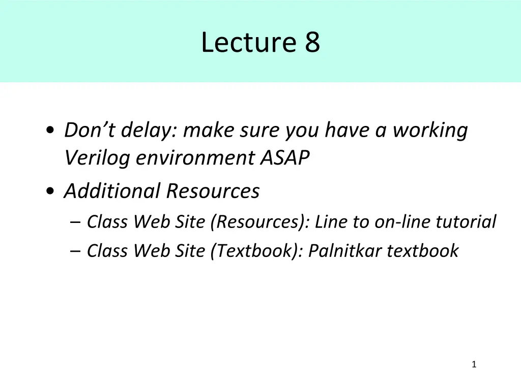
Lecture 8 Don t delay: make sure you have a working Verilog environment ASAP Additional Resources Class Web Site (Resources): Line to on-line tutorial Class Web Site (Textbook): Palnitkar textbook 1
Hardware Description Languages (HDLs)
Hardware Description Languages (HDLs) Benefits Complete, unambiguous specification of design Inputs, outputs, behavior, timing Simulation for design debug Synthesis for physical realization of design Several widely used ABEL primarily for PLDs VHDL (VHSIC Hardware Description Language) Verilog (1995, 2001) Numerous tools and vendors Capture, edit, simulate, synthesize 3
Modules Different types of module descriptions 1. Structural actual gates 2. Behavioral behavior, no structure 3. Dataflow simple output F(inputs) 4. Combination of above 5
Verilog Syntax Case sensitive module , Module , MODULE not same Reserved words are lower case (e.g. module ) User-defined identifiers (e.g. variables, modules, ports) no requirements Useful convention: use mixed case, leading capitals BufferFull not bufferfull or BUFFERFULL White space (e.g. spaces, line breaks ) generally ignored Use it to make your modules readable Comments // single line comments /* multiple line comments */ This is dataflow type of description 6
Verilog Syntax Identifiers Begin with letter or underscore Contain letters, digits, underscores, $ Number of bits radix 4 Valued Logic 0, 1, X, Z hexadecimal Literals (in language sense) n Bddd d n = (decimal) number of bits B = radix b = binary o = octal h = hexadecimal d = decimal ddd d = digits in designated radix R = 4 b1010; R = 4 hA; R = 4 o12; R = 4 d10; R = 10; octal 7
Operators in Verilog Operators Bit-wise Boolean Arithmetic and shift Logical Misc: concatenation, replication 8
Vectors in Verilog Vectors Signals or ports with width Bit select Zbus[5] Part select word1[15:8] 9
Verilog Instantiation and parameter lists Instantiating a module component name instance identifier Two forms of parameter lists By order of declaration By explicit port name 10
Verilog Dataflow Example: Full Adder CI A B CO S 0 0 0 0 0 0 0 1 0 1 0 1 0 0 1 0 1 1 1 0 1 0 0 0 1 1 0 1 1 0 1 1 0 1 0 1 1 1 1 1 11
A TestBench Testbench provides stimulus to module being tested Testbench must obey interface and protocol Interface: signal direction and width (e.g. bus) Protocol: timing and edge relationships Testbench facilitates response from module TestBench can be written to independently verify response Human can examine waveforms produced in simulation TestBench can be written to format response (e.g. table) for later examination or processing Testbench is a Verilog module! 14
A TestBench 0 1 1 0 1 0 0 0 1 0 0 0 Module TestBench TestBench instantiates module and provides necessary inputs, called test vectors Declares registers ( reg ) which will be connected to the module input ports Declares wires which will be connected to the module output ports 15
Testbench Example for previously presented Full Adder 16
A Complete Example Using Dataflow Style
A Complete Example Using Dataflow Style Design a circuit that takes as input a binary representation of a month, and an additional Boolean input LeapYear (LY) which is 1 if the current year is a leap year, and determines the number of days in the month. The circuit should have four outputs: D28, D29, D30, D31 which are true when the given month has exactly the indicated number of days. For example, if the month inputs indicate March, the output D31 will be 1 while D30, D29 and D28 will be 0. Use the fewest number of bits to encode the month input. 18
A Complete Example Using Dataflow Style Methodology (will vary with target implementation!) 1. Draw a black box , label inputs and outputs (I/Os) 2. Confirm formats, representations, timing of I/Os 3. Create a truth table 4. Use K-maps to obtain minimized/reduced equations 5. Translate equations to Verilog dataflow style syntax 6. Create a testbench to appropriately test the module Appropriate may mean exhaustive testing 7. Compile and test 8. Debug : Exam your results; if not as expected, work backwards 9. Bask in your success 19
Black Box and Truthtable Inputs Outputs Month Leap Year LY D28 D29 D30 D31 X 0 0 1 1 0 X 0 X 0 X 0 X 0 X 0 X 0 X 0 X 0 X 0 X 0 X X X X X X X X Encoded M3 M2 M1 M0 0 0 0 0 0 0 0 0 0 0 0 1 0 1 0 1 0 1 1 0 1 0 1 0 1 0 1 1 1 1 1 1 1 1 Jan Feb Feb Mar Apr May Jun Jul Aug Sep Oct Nov Dec -unused- -unused- -unused- -unused- 0 0 0 1 1 0 0 1 1 0 0 1 1 0 0 1 1 0 1 1 0 1 0 1 0 1 0 1 0 1 0 1 0 1 0 0 1 0 0 0 0 0 0 0 0 0 0 X X X X 0 0 0 0 1 0 1 0 0 1 0 1 0 X X X X 1 0 0 1 0 1 0 1 1 0 1 0 1 X X X X D31 4 M D30 DaysInMonth D29 LY D28 Use of X (don t care) in inputs reduces rows in truth table and helps to clarify functionality Use of X in outputs may lead to simpler Boolean equations Perhaps ask question about encoding used 20
K-Maps and Reduced Equations Inputs Outputs Month Leap Year LY D28 D29 D30 D31 X 0 0 1 1 0 X 0 X 0 X 0 X 0 X 0 X 0 X 0 X 0 X 0 X 0 X X X X X X X X Encoded M3 M2 M1 M0 0 0 0 0 0 0 0 0 0 0 0 1 0 1 0 1 0 1 1 0 1 0 1 0 1 0 1 1 1 1 1 1 1 1 Jan Feb Feb Mar Apr May Jun Jul Aug Sep Oct Nov Dec -unused- -unused- -unused- -unused- 0 0 0 1 1 0 0 1 1 0 0 1 1 0 0 1 1 0 1 1 0 1 0 1 0 1 0 1 0 1 0 1 0 1 0 0 1 0 0 0 0 0 0 0 0 0 0 X X X X 0 0 0 0 1 0 1 0 0 1 0 1 0 X X X X 1 0 0 1 0 1 0 1 1 0 1 0 1 X X X X 21
Verilog Dataflow Style Module module DaysInMonth(M3,M2,M1,M0,LY,D28,D29,D30,D31); Usually a block comment here with description of module, author, date, other pertinent information input M3,M2,M1,M0; // encoded value of month // Jan = 0000, Feb = 0001, etc input LY; output D28; output D29; output D30; output D31; // 1 if leap year D31 4 M // 1 if month has 28 days // 1 if month has 29 days // 1 if month has 30 days // 1 if month has 31 days D30 DaysInMonth D29 LY assign #6 D28 = ~M3 & ~M2 & ~M1 & M0 & ~LY; D28 assign #6 D29 = ~M3 & ~M2 & ~M1 & M0 & LY; assign #6 D30 = M3 & ~M0 | M2 & ~M1 & M0 | ~M3 & ~M2 & M1 & M0; assign #6 D31 = M3 & M0 | ~M3 & ~M0 | M2 & M1; endmodule D28 = M3 M2 M1 M0 LY D29 = M3 M2 M1 M0 LY D30 = M3 M0 + M2 M1 M0 + M3 M2 M1 M0 D31 = M3 M0 + M3 M0 + M2 M1 Delay 22
Verilog Testbench
Verilog Testbench for the same example module TestDays(); reg M3,M2,M1,M0; reg LY; wire D28, D29, D30, D31; Use of don t care inputs Ability to easily determine all input values for any test vector DaysInMonth D1 (M3,M2,M1,M0,LY,D28,D29,D30,D31); initial begin #10 LY = 1'bx; M3 = 1'b0; M2 = 1'b0; M1 = 1'b0; M0 = 1'b0; // Jan module DaysInMonth(M3,M2,M1,M0,LY,D28,D29,D30,D31); input M3,M2,M1,M0; // encoded value of month // Jan = 0000, Feb = 0001 input LY; output D28; // 1 if month has 28 days output D29; // 1 if month has 29 days output D30; // 1 if month has 30 days output D31; // 1 if month has 31 days // 1 if leap year #10 M3 = 1'b0; M2 = 1'b0; M1 = 1'b0; M0 = 1'b1; // Feb LY = 1'b0; // Not Leap Year #10 LY = 1'b1; // Leap Year #10 LY = 1'bx; M3 = 1'b0; M2 = 1'b0; M1 = 1'b1; M0 = 1'b0; // Mar #10 M3 = 1'b0; M2 = 1'b0; M1 = 1'b1; M0 = 1'b1; // Apr #10 M3 = 1'b0; M2 = 1'b1; M1 = 1'b0; M0 = 1'b0; // May #10 M3 = 1'b0; M2 = 1'b1; M1 = 1'b0; M0 = 1'b1; // Jun #10 M3 = 1'b0; M2 = 1'b1; M1 = 1'b1; M0 = 1'b0; // Jul #10 M3 = 1'b0; M2 = 1'b1; M1 = 1'b1; M0 = 1'b1; // Aug #10 M3 = 1'b1; M2 = 1'b0; M1 = 1'b0; M0 = 1'b0; // Sep #10 M3 = 1'b1; M2 = 1'b0; M1 = 1'b0; M0 = 1'b1; // Oct #10 M3 = 1'b1; M2 = 1'b0; M1 = 1'b1; M0 = 1'b0; // Nov #10 M3 = 1'b1; M2 = 1'b0; M1 = 1'b1; M0 = 1'b1; // Dec assign #6 D28 = ~M3 & ~M2 & ~M1 & M0 & ~LY; assign #6 D29 = ~M3 & ~M2 & ~M1 & M0 & LY; assign #6 D30 = M3 & ~M0 | M2 & ~M1 & M0 | ~M3 & ~M2 & M1 & M0; assign #6 D31 = M3 & M0 | ~M3 & ~M0 | M2 & M1; endmodule #20 $finish(); end endmodule 24
The Timing Diagram 25 Note how easy to read, determine if all input combinations used
A Better Solution: Buses (Vectors) module DaysInMonth(M,LY,D28,D29,D30,D31); input [3:0] M; // encoded value of month // Jan = 0000, Feb = 0001, etc input LY; output D28; output D29; output D30; output D31; // 1 if leap year D31 4 M // 1 if month has 28 days // 1 if month has 29 days // 1 if month has 30 days // 1 if month has 31 days D30 DaysInMonth D29 LY assign #6 D28 = ~M[3] & ~M[2] & ~M[1] & M[0] & ~LY; D28 assign #6 D29 = ~M[3] & ~M[2] & ~M[1] & M[0] & LY; assign #6 D30 = M[3] & ~M[0] | M[2] & ~M[1] & M[0] | ~M[3] & ~M[2] & M[1] & M[0]; assign #6 D31 = M[3] & M[0] | ~M[3] & ~M[0] | M[2] & M[1]; endmodule 26
A Better Solution: Buses (Vectors) module TestDays(); Port types must match reg [3:0] M; reg LY; wire D28,D29,D30,D31; module DaysInMonth(M,LY,D28,D29,D30,D31); DaysInMonth D1 (M,LY,D28,D29,D30,D31); input [3:0] M; // encoded value of month // Jan = 0000, Feb = 0001, etc initial begin #10 LY= 1'bx; M= 4 b0000; // Jan input LY; output D28; output D29; output D30; output D31; // 1 if leap year // 1 if month has 28 days // 1 if month has 29 days // 1 if month has 30 days // 1 if month has 31 days #10 M= 4 b0001; // Feb LY= 0; #10 LY= 1; #10 LY= 1'bx; M= 4 b0010; // Mar #10 M= 4 b0011; // Apr #10 M= 4 b0100; // May #10 M= 4 b0101; // Jun #10 M= 4 b0110; // Jul #10 M= 4 b0111; // Aug #10 M= 4 b1000; // Sep #10 M= 4 b1001; // Oct #10 M= 4 b1010; // Nov #10 M= 4 b1011; // Dec assign #6 D28 = ~M[3] & ~M[2] & ~M[1] & M[0] & ~LY; assign #6 D29 = ~M[3] & ~M[2] & ~M[1] & M[0] & LY; assign #6 D30 = M[3] & ~M[0] | M[2] & ~M[1] & M[0] | ~M[3] & ~M[2] & M[1] & M[0]; assign #6 D31 = M[3] & M[0] | ~M[3] & ~M[0] | M[2] & M[1]; endmodule #20 $finish(); end endmodule 27
TestBenches with Buses Buses bundled together in waveform display improve readability 28
Alternative TestBenches with Buses module TestDays(); reg [3:0] M; reg LY; wire D28, D29, D30, D31; Most tools provide a means to change display radix DaysInMonth D1 (M,LY,D28,D29,D30,D31); initial begin #10 LY= 1'bx; M= 0; // Jan #10 M= 1; // Feb LY= 0; #10 LY= 1; #10 LY= 1'bx; M= 2; // Mar #10 M= 3; // Apr #10 M= 4; // May #10 M= 5; // Jun #10 M= 6; // Jul #10 M= 7; // Aug #10 M= 8; // Sep #10 M= 9; // Oct #10 M= 10; // Nov #10 M= 11; // Dec #20 $finish(); end endmodule 29
TestBenches with Behavioral Code module TestDays(); reg [3:0]M; reg LY; wire D28, D29, D30, D31; Behavioral code to facilitate creation of test vectors DaysInMonth D1 (M, LY, D28, D29, D30, D31); Behavioral code for automating checking e.g. consider a method to verify a multiplier design initial begin for (M = 0; M <= 11; M=M+1) begin LY = 0; #10; LY = 1; #10; end $finish(); end endmodule 30
D28 = M3 M2 M1 M0 LY D29 = M3 M2 M1 M0 LY D30 = M3 M0 + M2 M1 M0 + M3 M2 M1 M0 D31 = M3 M0 + M3 M0 + M2 M1 31
Verilog Structural Style Module module DaysInMonth(M,LY,D28,D29,D30,D31); Reflects actual implementation. Primitives: or, and, nand, xor, xnor, nor, not Variable number of inputs Output is first port Wires used to connect gate outputs/inputs Comma separated list will share tpd Can have asymmetric delays (tPLH tPHL) input [3:0]M; // encoded value of month // Jan = 0000, Feb = 0001, etc input LY; // 1 if leap year output D28; // 1 if month has 28 days output D29; // 1 if month has 29 days output D30; // 1 if month has 30 days output D31; // 1 if month has 31 days wire T1,T2,T3,T4,T5,T6; wire M3bar,M2bar,M1bar,M0bar,Lybar; not #(3,3) and #(5,4) and #(5,4) or #(5,5) and #(5,4) or #(5,5) endmodule U1a(M3bar,M[3]), U1b(M2bar,M[2]), U1c(M1bar,M[1]), U1d(M0bar,M[0]), U1e(LYbar,LY); Note: can use same testbench used with dataflow (maybe need to accommodate different Tpd) U2a(D28,M3bar,M2bar,M1bar,M[0],LYbar), U2b(D29,M3bar,M2bar,M1bar,M[0],LY); U3a(T1,M[3],M0bar), U4a(T2,M[2],M1bar,M[0]), U5a(T3,M3bar,M2bar,M[1],M[0]); U6a(D30,T1,T2,T3); U3b(T4,M[3],M[0]), U3c(T5,M3bar,M0bar), U3d(T6,M[2],M[1]); U6b(D31,T4,T5,T6); 32
Hierarchical Structural Description 33 Note that this is structural and hierarchical
Sources Prof. Mark G. Faust John Wakerly


")
")