Analog-to-Digital Conversion in Microcontrollers
Learn about the process of analog-to-digital conversion (ADC) in microcontrollers, and how it helps in transforming analog signals into digital data. Explore the principles, types of ADC, digitalization, signal processing, and more.

Uploaded on | 0 Views
Download Presentation

Please find below an Image/Link to download the presentation.
The content on the website is provided AS IS for your information and personal use only. It may not be sold, licensed, or shared on other websites without obtaining consent from the author. If you encounter any issues during the download, it is possible that the publisher has removed the file from their server.
You are allowed to download the files provided on this website for personal or commercial use, subject to the condition that they are used lawfully. All files are the property of their respective owners.
The content on the website is provided AS IS for your information and personal use only. It may not be sold, licensed, or shared on other websites without obtaining consent from the author.
E N D
Presentation Transcript
A/D konverter (ADC) A/D talak t
ADC A mikrovez rl csak digit lis adatokat k pes kezelni (0 s 1). A val s vil g jelei nagyr szt anal g jelek (szonzorok): h m rs klet, nedvess g. Ahhoz hogy a mikrovez rl fel dolgozni a bemeneti anal g adatokat, digit liss kell hogy alak tsa ket. Erre szolg l az A/D talak t . nyom s, tudja
Digitalizls plda Az anal g jel id ben s amplit d ban is folytonos. Mind a k t rt k diszkretiz l s val nyerj k a digit lis jelet.
A jel fogadsa ltal nos esetben, a jel (adat) fogad sa egy 3 l p sb l ll folyamat. 1. Egy fizikai mennyis gt l f gg en, a szenzor a kimenet n anal g elektromos fesz lts get ad. 2. Az egyszer bb feldolgoz s miatt, az anal g jelet digit liss alak tjuk anal g-digit lis talak t (ADC) seg ts g vel. 3. A digit lis jelet feldolgoz s c lj b l a mikrovez rl nek tov bb tjuk.
Analg bemenetek A korszer mikrovez rl k a bemenet k n be p tett ADC-vel rendelkeznek, ez rt k ls ramk r hozz ad sa nem sz ks ges.
Az ADC jellemzi M k d si elv: szukcessz v approkszim ci 6 kan lis (multipleksz lt), 10 bit-es rezol ci (eredm ny: 0-1023 k z tt)
ADC Referens fesz lts g 5V, az sszes anal g fesz lts get az ekvivalens ADC rt kre alak tjuk. A (0V-5V) tartom nyt 210= 1024 l p sre osztjuk. A bemeneti 0V-b l 0 lesz, a bemeneti 5V- b l 1023 lesz, a bemeneti 2.5V-b l 523 lesz, stb.
ADC tpusok Szukcessz v approkszim ci , Flash konverter (nagy sebess g, alacsony rezol ci mivel sok kompar torra van sz ks g). A 8-bites kompar tor sz ks ges. Fontos fogalmak: (prescaler), ADC regiszterek. talak t hoz 256 ADC el oszt
ADC prescaler Az ADC periodikus id intervallumokban alak tja t az anal g jelet. Ezt az intervallumot az oszcill tor frekvenci ja hat rozza meg. Az ADC 50kHz-200kHz tarom nyban m k dik. A CPU rajel sokkal nagyobb, ez rt sz ks ges az oszt s. Az ADC frekvenci j t gy nyerj k, hogy a CPU frekvenci j t elosztjuk az el oszt rt k vel.
ADC prescaler Az oszt si ar nyok el re meg vannak hat rozva: 2, 4, 8, 16, 32, 64 s 128. Ha p ld ul prescaler = 64: F_ADC = F_CPU/64 F_CPU = 16MHz, F_ADC = 16M/64 = 250kHz A k rd s hogy melyik frekvenci t v lasszuk?
ADC prescaler A frekvencia meg a pontoss g k z tt kompromisszumot kell k tni. A nagyobb frekvecnia kisebb pontoss got jelent, s ford tva.
ADC regiszterek ADMUX ADC Multiplexer Selection Register Bits 7-6 : Referens fesz lts g kiv laszt sa
Referens feszltsg Az ADC-nek referens fesz lts g sz ks ges, amelyik az AREF, AVCC s GND-vel van meghat rozva. A VCC ingadozhat!
ADC registri ADLAR ADC left adjust result 1 : az eredm ny balra van igaz tva Bit 4-0: ADC kan lis nak meghat roz sa ADCSRA ADC Control and Status Register A
ADCSRA Bit 7 ADEN ADC Enable As the name says, it enables the ADC feature. Unless this is enabled, ADC operations cannot take place across PORTA i.e. PORTA will behave as GPIO pins. Bit 6 ADSC ADC Start Conversion Write this to 1 before starting any conversion. This 1 is written as long as the conversion is in progress, after which it returns to zero. Normally it takes 13 ADC clock pulses for this operation. But when you call it for the first time, it takes 25 as it performs the initialization together with it. Bit 5 ADATE ADC Auto Trigger Enable Setting it to 1 enables auto-triggering of ADC. ADC is triggered automatically at every rising edge of clock pulse. View the SFIOR register for more details.
ADCSRA Bit 4 ADIF ADC Interrupt Flag Whenever a conversion is finished and the registers are updated, this bit is set to 1 automatically. Thus, this is used to check whether the conversion is complete or not. Bit 3 ADIE ADC Interrupt Enable When this bit is set to 1 , the ADC interrupt is enabled. This is used in the case of interrupt-driven ADC. Bits 2:0 ADPS2:0 ADC Prescaler Select Bits The prescaler (division factor between XTAL frequency and the ADC clock frequency) is determined by selecting the proper combination from the following.
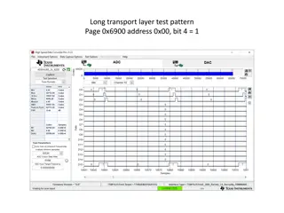
ADCL s ADCH ADC adatregiszterek qw
ADC init void adc_init() { // AREF = AVcc ADMUX = (1<<REFS0); // ADC Enable and prescaler of 128 // 16000000/128 = 125000 ADCSRA = (1<<ADEN)|(1<<ADPS2)|(1<<ADPS1)|(1<<ADPS0); }
ADC read uint16_t adc_read(uint8_t ch) { // select the corresponding channel 0~7 // ANDing with 7 will always keep the value // of ch between 0 and 7 ch &= 0b00000111; // AND operation with 7 ADMUX = (ADMUX & 0xF8)|ch; // clears the bottom 3 bits before //ORing // start single convertion // write 1 to ADSC ADCSRA |= (1<<ADSC); // wait for conversion to complete // ADSC becomes 0 again // till then, run loop continuously while(ADCSRA & (1<<ADSC)); return (ADC); }
")