Implement Monostable Multivibrator Circuit with IC555 for CEII Lab
Learn how to design and study a monostable multivibrator circuit using IC555 Timer for the CEII Lab. Explore the theory, functional block diagram of IC555, and the operation of monostable multivibrators. Experiment with the apparatus required and understand the working principles involved in generating single pulses of desired duration.

Download Presentation

Please find below an Image/Link to download the presentation.
The content on the website is provided AS IS for your information and personal use only. It may not be sold, licensed, or shared on other websites without obtaining consent from the author. If you encounter any issues during the download, it is possible that the publisher has removed the file from their server.
You are allowed to download the files provided on this website for personal or commercial use, subject to the condition that they are used lawfully. All files are the property of their respective owners.
The content on the website is provided AS IS for your information and personal use only. It may not be sold, licensed, or shared on other websites without obtaining consent from the author.
E N D
Presentation Transcript
To Design and Implement Monostable Multivibrator Circuit Using IC555 LAB:- CEII (SEM V EXTC)
AIM To Design and Study the operation of monostable multivibrator using IC555 Timer LAB:- CEII (SEM V EXTC)
Apparatus 555 Timer IC Resistor ( Values as per design) Capacitors (Values as per Design) Function Generator CRO Bread Board Connecting Wires and Probes LAB:- CEII (SEM V EXTC)
Theory Functional Block Diagram of IC555:- Reference:- www.electronics.dit.ie LAB:- CEII (SEM V EXTC)
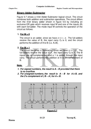
Functional Block Diagram of IC555:- Timer IC consists of two comparators A resistive voltage divider generating the required reference voltage for the two comparator SR flip-flop Output Buffer Discharging Transistor T1 LAB:- CEII (SEM V EXTC)
Multivibrators It is a circuit which can have no, one or two stable states of operation. Types :- 1. Astable Multivibrator:- No stable state 2. Monostable Multivibrator:- One stable state 3. Bistable Multivibrator :- Two stable states LAB:- CEII (SEM V EXTC)
Monostable Multivibrator using IC555 8 Vcc 4 Reset R Threshold Comparator Ra 2V 3 +V Output - Q R cc 3 + 6 -V R Trigger +V - 2 S Q 1V 3 + -V cc Trigger Comparator Control Flip-Flop 7 R C Monstable Multivibrator One-Shot 1 Fig 1. :Monostable Multivibrator using IC555 Reference:- https://electrosome.com/astable-multivibrator-555-timer/ LAB:- CEII (SEM V EXTC)
Monostable Multivibrator The monostable multivibrator is also called as one shot, as it generates a single pulse of desired duration after getting a trigger signal. The time constant of the externally connected resistor- capacitor to IC 555 determines the length of the pulse. LAB:- CEII (SEM V EXTC)
Monostable Multivibrator The Monostable Multivibrator will be in its stable state (Output LOW) until it is triggered. When a negative trigger is applied to the trigger pin of 555 Timer, output of lower comparator will become HIGH and output of upper comparator will be LOW, since the capacitor voltage is zero. This makes the output HIGH. The Discharge transistor turns OFF and the capacitor starts charges through resistor R to Vcc. After the negative trigger, output of lower comparator becomes LOW and that of upper comparator remains LOW. Since both inputs of the SR Flip Flop are LOW, output will not change, so the output is HIGH. LAB:- CEII (SEM V EXTC)
Waveform Monostable Reference :- http://www.learnabout-electronics.org/Oscillators/osc45.php LAB:- CEII (SEM V EXTC)
Design Equations 1. The charging equations of capacitor is given by:- Vc = Vcc[ 1-e-t/RC] Where, Vc= capacitor voltage t= on time 2. During on time duration of output pulse capacitor voltage reaches a level of 2/3Vcc Hence 2/3 Vcc= Vcc[ 1-e-Ton/RC] Ton = 1.1 RC Where , R = Externally connected resistor C = Externally connected capacitor LAB:- CEII (SEM V EXTC)
Design Statement for Implementation Design a monostable multivibrator using IC555 for Vcc= 12V and pulse width of 1.65msec. Soln:- Pulse width = Ton= 1.1 R C Hence, 1 msec = 1.1 RC Let C= 0.1 uF 1.65*10-3 = 1.1 R * 0.1 * 10-6 R= 15 K LAB:- CEII (SEM V EXTC)
Procedure 1. Mount the circuit as per design on bread board. 2. Apply negative triggering pulse of 1 KHz at pin 2 and Vcc= 5V 3. Observe the output and capacitor voltage waveforms on CRO. 4. Compare the obtained results with designed values. LAB:- CEII (SEM V EXTC)
Observation Map out the time period of the output wave form and compare it with the given one. Parameter Designed Observed Ton LAB:- CEII (SEM V EXTC)
Results and Discussion The waveform is observed and verified with required condition. LAB:- CEII (SEM V EXTC)
Questions 1. What is the working principle of Monostable Multivibrator? 2. Why the name is given as monostable? LAB:- CEII (SEM V EXTC)