Reconfigurable Multi-Radio Device Overview
Explore the concept of reconfigurable multi-radio devices allowing for dynamic radio movement across links without re-association, enhancing efficiency and flexibility in wireless communication setups.

Download Presentation

Please find below an Image/Link to download the presentation.
The content on the website is provided AS IS for your information and personal use only. It may not be sold, licensed, or shared on other websites without obtaining consent from the author. If you encounter any issues during the download, it is possible that the publisher has removed the file from their server.
You are allowed to download the files provided on this website for personal or commercial use, subject to the condition that they are used lawfully. All files are the property of their respective owners.
The content on the website is provided AS IS for your information and personal use only. It may not be sold, licensed, or shared on other websites without obtaining consent from the author.
E N D
Presentation Transcript
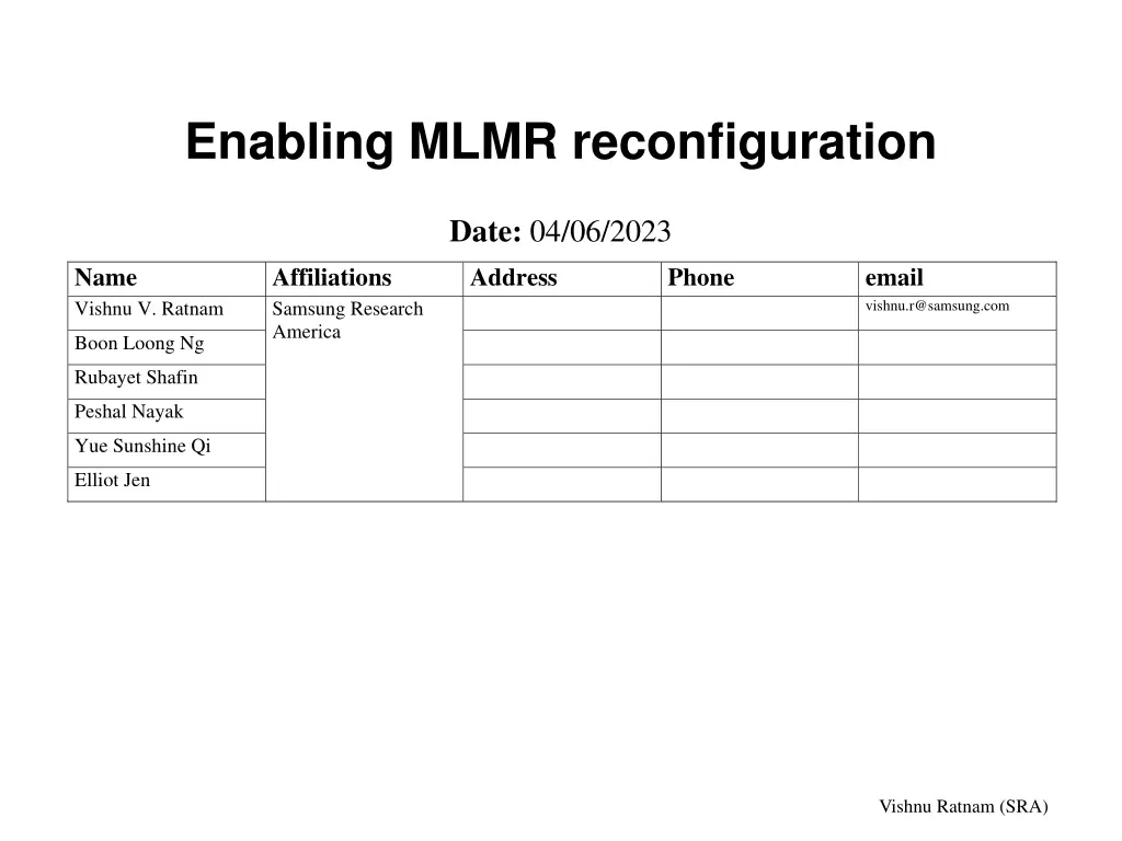
Enabling MLMR reconfiguration Date: 04/06/2023 Name Vishnu V. Ratnam Affiliations Samsung Research America Address Phone email vishnu.r@samsung.com Boon Loong Ng Rubayet Shafin Peshal Nayak Yue Sunshine Qi Elliot Jen Vishnu Ratnam (SRA)
Comment Resolution CID Clause Comment Proposed change A reconfigurable multi-radio AP or non-AP MLD should be capable of moving its radios quasi-statically across the enabled links based on the requirement. A mechanism to seemlessly indicate the updated MCS-NSS set for each of such links without the need for re-association is required. The commenter will bring forth a solution to the problem. 17989 35.3.16.2 Vishnu Ratnam (SRA)
Motivation Reconfigurable MLMR device: A multi-radio device that can move radios across links, e.g., EMLMR capable device. A reconfigurable MLMR device should be quasi-statically able to move radios across its links. This is useful when bandwidth/load/OBSS interference of one link is becomes better than another link. When one of the link is removed by the AP MLD. The RSSI of the different links change due to mobility etc. When such a reconfiguration happens at a non-AP MLD or AP MLD, the following can change: The maximum NSS that each of the links can support for TX and RX. The NSS that can be supported at each MCS can change. This feature is beneficial to both an AP MLD and a non-AP MLD implementation for efficiency of hardware. However here we focus on non-AP MLD case only. Use cases Example operation NSS=2 RFchain1 STA1 STA1 Configuration 1 STA2 RFchain2 STA2 NSS=2 2.4 GHz 5 GHz MLMR MLD 2 MLMR MLD 1 NSS=4 RFchain1 STA1 STA1 Configuration 2 STA2 RFchain2 STA2 NSS=0 MLMR MLD 2 MLMR MLD 1 NSS=0 RFchain1 STA1 STA1 2.4 GHz 5 GHz Configuration 3 STA2 RFchain2 STA2 NSS=4 Vishnu Ratnam (SRA) MLMR MLD 2 MLMR MLD 1
Problem As per the baseline spec, the EHT-MCS and NSS Sets are disclosed by a non-AP MLD in (Re)association request frames and probe request frames. Furthermore, these are per-link indications, i.e., are indicated separately for each link. A mechanism to update the EHT-MCS and NSS sets for one or more links without the need for re-association is required. Vishnu Ratnam (SRA)
Option 1: Using the OM procedure When performing association, a reconfigurable MLD shall report, for each MCS the highest NSS values it supports (across all possible configurations) in the EHT-MCS Map subfield of the Supported EHT MCS and NSS Set field of the EHT capabilities element transmitted by it. For example, for the MLD2 on slide 2, the EHT-MCS Map can be: RX NSS at MCS 0-9 RX NSS at MCS 10-11 RX NSS at MCS 12-13 TX NSS at MCS 0-9 TX NSS at MCS 10-11 TX NSS at MCS 12-13 4 4 4 4 4 4 Note: The indicated NSS can be more than what the non-AP supports in the current configuration used for performing the association To indicate the actual number of supported NSS, after association, each STA of the MLD shall use the operating mode (OM) notification/indication procedure. The indication should follow immediately after association to prevent frame loss. For example, if MLD2 in slide 2 is in configuration 1, each of STA 1 and STA2 of MLD2 can transmit an Operating Mode Notification frame or can transmit an OM Control field in a frame that sets the Rx NSS and Tx NSS to 2 streams. RX NSS at MCS 0-9 RX NSS at MCS 10-11 RX NSS at MCS 12-13 ,2 min 4 4 4 Reported in EHT Capabilities element Indicated using operating mode indication If in a configuration, the number of NSS for a STA is zero, the STA can use power management to prevent frame exchanges on that link or can use TID-to-link mapping procedure to disable that link. Vishnu Ratnam (SRA)
Option 1: Using the OM procedure When the reconfigurable non-AP MLD changes its configuration, it shall perform the following procedures sequentially: 1. The STA(s) affiliated with the non-AP MLD that intend to reduce the RX NSS shall transmit an OM Notification frame or OMI control field indicating the reduced NSS values for transmission and reception. 2. After waiting for enough time after successful transmission of the OM Notification frame or OMI Control field, the non-AP MLD should switch the radios to reach new configuration. 3. After the reconfiguration, the STA(s) affiliated with the non-AP MLD on which the NSS has increased due to the reconfiguration shall transmit an OM Notification frame or an OMI control field to indicate the increased NSS values for transmission and reception. NSS=2 NSS=3 RFchain1 STA1 RFchain1 STA1 STA2 transmits OMN frame or OMI control field STA1 transmits OMN frame or OMI control field NSS=2 NSS=1 RFchain2 STA2 RFchain2 STA2 MLMR AP MLD Configuration 1 MLMR AP MLD Configuration 2 Issues with option 1: Setting a RX NSS or TX NSS using OM is oversimplified and doesn t always work. RX NSS at MCS 0-9 RX NSS at MCS 10-11 RX NSS at MCS 12-13 RX NSS at MCS 0-9 RX NSS at MCS 10-11 RX NSS at MCS 12-13 ,2 min 4 4 2 2 2 1 Indicating an optimistic EHT-MCS and NSS Set during association (more than the current configuration can support) is a poor design. There can be a delay between the indication of the MCS and NSS Set and the Operating Mode indication. During this time there can be frame loss. Vishnu Ratnam (SRA)
Option 2: Using EML OMN frame A non-AP MLD shall indicate an update to the EHT-MCS and NSS map for an affiliated STA by transmitting an EML Operating Mode notification (OMN) frame to the AP MLD it is associated with. The transmitting STA affiliated with a non-AP MLD shall set the NSS Update Mode bit in the EML OMN to 1 to indicate that the frame provides updated MCS and NSS Maps for a STA affiliated with the non-AP MLD. When the NSS Update Mode bit is set to 1: Link Bitmap indicates the link for which the supported MCS and NSS Set update is being included. This bitmap field reuses the EMLSR/EMLMR Link Bitmap, and only one bit of the bitmap shall be set to 1. The supported MCS and NSS Set field includes the MCS Maps for the link indicated in the link ID bitmap. This field reuses the EMLMR Supported MCS and NSS Set field. The MCS Map Count field in the MCS Map Count Control field indicates the number of BWs {<=80, 160, 320} MHz for which the MCS and NSS Maps are included in the Supported MCS and NSS Set. The Supported MCS and NSS Set shall replace any indication provided in a previous EML OMN or in the Supported EHT MCS and NSS Set field of the EHT capabilities element for that link. The change shall be applicable after receiving an EML OMN Response frame or after a Transition Timeout delay, whichever is shorter. The indication is only for one link at a time, so the sequence of indication steps are similar to option 1. Note: that this option has minimal changes to existing EML Control field in D3.0. 0 0 1 0 0 0 0 0 0 0 0 0 0 0 0 0 MCS Map (BW 80) MCS Map (BW=160) MCS Map (BW=320) Octets: 0 or 3 0 or 3 0 or 3 EMLSR mode EMLMR mode EMLSR Parameter Update Control NSS Update Mode Reserved Link Bitmap MCS Map count control Supported MCS and NSS Set Bits: 1 1 1 1 4 0 or 16 0 or 8 variable
Option 3: Using Reconfig. ML element A non-AP MLD shall indicate an update to the EHT-MCS and NSS map for an affiliated STA by including a Reconfiguration ML element in a frame it transmits to the AP MLD it is associated with. The Reconfiguration ML element shall include a per STA profile sub-element in the Link Info field, corresponding to each of the links whose NSS will be affected by the reconfiguration. For indicating a change in the EHT-MCS and NSS map for a STA, the Operation Update Type in the STA Info Field shall be set to 1 (NSS Update). When Operation Update Type subfield is set to 1, the format of the STA Info field for a STA shall be as follows: The STA MAC Address, and Operation Parameters are not present. The MCS and NSS Update field may be present. The MCS and NSS Update field shall have an MCS Map Count Control subfield and a Supported MCS and NSS Set field that is applicable to the corresponding STA (similar behavior as in option 2). The Supported MCS and NSS Set shall replace any indication provided in a previous Reconfig. ML element or in the Supported EHT MCS and NSS Set field of the EHT capabilities element. The new indicated EHT MCS and NSS set shall be applicable after the successful transmission of the frame containing the reconfiguration ML element. Per-STA profile subelement Operation Update Type Value Name 0 Operation Parameter Update 1 NSS Update STA Info Length STA MAC Address Operation Parameters MCS and NSS Update 2-15 Reserved Octets: 1 0 or 6 0 or 2 0 or variable MCS Map Count Control Supported MCS and NSS Set Octets: 1 variable
FAQ Q: Why should this issue be resolved in 802.11be? Ans: 802.11be already supports EMLMR mode of operation that involves a reconfigurable non-AP MLD that can swiftly move radios across links after receiving an initial frame. The feature discussed here is to enable quasi-static movement of radios across links, and it is a basic required feature for reconfigurable MLDs. When EMLMR mode is already supported, we should not leave out a basic feature that such reconfigurable MLDs need. Vishnu Ratnam (SRA)
Straw polls SP1: Do you agree to support reconfigurable non-AP MLD operation in 802.11be. Yes No Abstain Result: SP2: What is your preferred resolution to CID 17989? Option 1 Option 2 Option 3 Result: Note: This SP is for feedback so that presenter can prepare an appropriate CR document. Vishnu Ratnam (SRA)
Backup slides Vishnu Ratnam (SRA)
How is max NSS at each MCS indicated? Clause 9.4.2.3.313.4: For each of its STA, an MLD indicates a set of supported maximum NSS (for TX and RX respectively) for each modulation and coding scheme (MCS) in the EHT-MCS Map subfield of the Supported EHT MCS and NSS Set field of the EHT capabilities element. The EHT-MCS field indicates the combinations of MCS {0-13} and NSS supported by a STA for transmission and reception. The EHT capabilities element is a per link indication and is transmitted by a non-AP MLD in: Mandatorily carried in an Association/reassociation request frame sent by an EHT non-AP MLD. Mandatorily present in a probe request frame sent by an EHT non-AP MLD. Mandatorily present in a TDLS Discovery Request/Response frame if the transmitting STA belongs to an EHT MLD. The EHT capabilities element is a per link indication and is transmitted by AP MLD in: Mandatorily carried in a beacon frame transmitted by an EHT AP MLD. Mandatorily carried in an Association/reassociation response frame if the AP belongs to an EHT AP MLD. Mandatorily carried in a probe response frame if the AP belongs to an EHT AP MLD.
Changing supported NSS by using OM Clause 11.40 and Clause 26.9: The spec also defines a power saving mechanism for a STA called operating mode change . By using an operating mode change, a STA can change its operating bandwidth and/or the maximum NSS that it can support. Thus, it can save power by reducing bandwidth or number of spatial streams when required. A STA can change its RX operating mode by either: (see backup slides for details) Transmitting an Operating Mode Notification frame, which is a VHT Action frame (class 3 management). Transmitting an Operating Mode Notification element inside a beacon frame, (Re)association request/response frames. Transmitting an OM Control subfield or EHT OM Control subfield in an A-control field of a QoS Data, QoS Null or Class 3 Management frames. (This is not very useful for AP since can t be broadcast.) A non-AP STA can change its TX operating mode by either: (see backup slides for details) Transmitting an OM Control subfield or EHT OM Control subfield in an A-control field of a QoS Data, QoS Null or Class 3 Management frames. For any MCS, that the max receive Nss that a nonAP STA can support is equal to the smaller of: The value of the Rx Max Nss That Supports Specified MCS subfield for the given EHT-MCS The maximum supported Nss as indicated by the value of the Rx NSS field of the Operating Mode Notification frame or the Operating Mode Notification element if the value of Rx NSS Type is 0, or by the value of the Rx NSS field of the OM Control subfield if EHT OM Control subfield is not present in the same A-Control field, or by the value of the Rx NSS Extension field of the EHT OM Control subfield combined with the value of the Rx NSS field of the OM Control subfield Note that this operating mode notification is a per-link indication. Vishnu Ratnam (SRA)