Understanding Logic Gates and Circuits
Learn about the functions of logic gates, how to design circuits using them, and construct truth tables. Explore the basics of AND, OR, NOT, NAND, NOR, and XOR gates. Understand how these gates operate and their applications in digital circuits.

Download Presentation

Please find below an Image/Link to download the presentation.
The content on the website is provided AS IS for your information and personal use only. It may not be sold, licensed, or shared on other websites without obtaining consent from the author. If you encounter any issues during the download, it is possible that the publisher has removed the file from their server.
You are allowed to download the files provided on this website for personal or commercial use, subject to the condition that they are used lawfully. All files are the property of their respective owners.
The content on the website is provided AS IS for your information and personal use only. It may not be sold, licensed, or shared on other websites without obtaining consent from the author.
E N D
Presentation Transcript
Logic Gates The Basic Gates and Circuits
Recall Add the following Binary numbers: 10101111 + 10110111
Recall Multiply the following binary number by 2. (Hint: Logical binary shift) 10110111
Lesson Objectives Understand the functions of the main logic gates Know how to design simple circuits using logic gates Understand how to construct a Truth Table for simple logic circuits
Logic Gates A logic gate is a digital circuit which either allows a signal to pass or stops it Logic gates allow the computer to: Add Divide Multiply Do simple Yes and No reasoning
Overview There are six basic logic gates: AND, OR, NOT, NAND, NOR, and XOR AND GATE AND GATE OR GATE OR GATE NOT GATE NOT GATE
NOT AND OR Exclusive OR
Truth Tables Every Logic Gate has a TruthTableto describe the output of a particular Boolean logic operation. Inputs and outputs are labelled A A 0 0 1 1 B B 0 1 Y Y There are two inputs giving four possible values 0 1
AND Gates Gives a TRUE result (1) if both inputs are TRUE (1) A B Y A A 0 0 1 1 B B 0 1 0 1 Y = A Y = A AND B AND B 0 0 0 1
OR Gates Gives a TRUE result (1) if any input value is TRUE (1) A B Y A A 0 0 1 1 B B 0 1 0 1 Y = A Y = A OR B 0 1 OR B 1 1
NOT Gates Changes the input value to its opposite value This Logic Gate only has one input A Y A 0 1 Y = NOT A 1 0
NAND Gates Gives an output of 1 if both input values are NOT 1 (the opposite of an AND Gate) A B Y A 0 0 1 1 B 0 1 0 1 A NAND B 1 1 1 0
NOR Gates Gives an output of 1 if both the inputs are 0 (the opposite of an OR Gate A B Y A 0 0 1 1 B 0 1 0 1 A NOR B 1 0 0 0
XOR Gates Gives an output of 1 if the two input values are different A B Y A 0 0 1 1 B 0 1 0 1 A XOR B 0 1 1 0
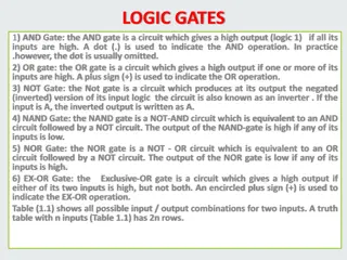
Summary Name Symbol Description AND Gate Output is 1 only if all inputs are 1 NAND Gate NOT-AND Gate Opposite of AND Gate. Output is 1 only if any input is NOT 1 OR Gate Output is 1 if either input is 1 Output is 0 only if both inputs are 0 NOR Gate NOT-OR Gate Opposite of OR Gate Output is 1 only if both inputs are 0 XOR Gate Exclusive OR gate - Output is only 1 if either input is 1. If both inputs are 1, the output is 0 NOT Gate Reverses the input Also known as an inverter gate
Produce a Truth Table for the following logic circuit P A B R Q X C
Intermediate Values P Q Input Value Output A 0 0 0 0 1 1 1 1 B 0 0 1 1 0 0 1 1 C 0 1 0 1 0 1 0 1 R X
P = A AND B P = A AND B Q = B NOR C Q = B NOR C Intermediate Values P Q 0 0 0 0 0 0 1 1 0 Input Value Output A 0 0 0 0 1 1 1 1 B 0 0 1 1 0 0 1 1 C 0 1 0 1 0 1 0 1 R X 1 0 0 0 1 0 0
R = P OR Q R = P OR Q X = C XOR R X = C XOR R Intermediate Values P Q 0 0 0 0 0 0 1 1 0 Input Value Output A 0 0 0 0 1 1 1 1 B 0 0 1 1 0 0 1 1 C 0 1 0 1 0 1 0 1 R 1 0 0 0 X 1 1 0 1 0 0 0 1 0 0 1 1 1 0 1 1 0 1 1
Exercise One C A X D E B
Exercise One Truth Table Input Value Intermediate Values Output A B C 0 0 0 1 D E 1 0 0 0 X 1 1 0 0 0 0 0 1 1 1 0 0 0 1 1 0 1 1 1 1
Exercise Two Truth Table Input Value Intermediate Values C D 1 1 0 0 1 Output E 0 1 0 0 F 1 0 1 1 A B X 1 1 1 1 1 1 0 1 1 0 0 0 1 1 0 1 1 1 1
Exercise Three A D F X E B C
Exercise Three Truth Table Input Value Intermediate Values D E 0 0 1 1 0 1 1 1 1 0 Output F 1 1 0 1 0 0 0 1 A B C X 1 1 1 1 1 1 1 0 0 0 0 0 0 0 1 0 1 0 1 1 0 0 1 1 0 0 0 1 1 1 1 1 1 1 0 0 0 1 1 1 0 1 1 1 1 1
Exercise Four D A F G X B E C
Exercise Four Truth Table Input Value Intermediate Values D E 0 0 1 1 0 1 1 1 1 0 Output A 0 B 0 C 0 X F 1 1 0 0 0 0 0 0 G 0 0 0 0 0 0 0 1 0 0 1 0 0 0 1 0 0 0 0 1 0 0 1 1 0 1 1 1 1 1 1 1 0 0 1 0 0 1 0 0 1 0 1 1 1 1 1 0 1 1 1
Exercise Five - Tricky Question? A X B [2] What Gate does this circuit produce? [1] OR Gate
Summary Name Symbol Description AND Gate NAND Gate OR Gate NOR Gate XOR Gate NOT Gate
Exercise One C A X D E B
Exercise Two C E A F X D B
Exercise Three A D F E B C
Exercise Four D A F G B E C